|
Converter-Concepts / Cooling |

|
 |
|
 |
|
 |
CERN
|
SY-EPC
|
EDMS
|
PROJECTS
|
ODF
/
OOXML
|
|
CERN
|
SY-EPC
|
EDMS
|
PROJECTS
|
ODF
/
OOXML
|

|
|
|
||||||||||||||||||||||||||||||||||||
| CERN Water Distribution LHC Network | Data | ||
|---|---|---|---|
| Label | Value | Unit | |
| Absolute Nominal operating pressure | P.in, P.out | [1..16] | [bars] |
| Nominal designed available pressure drop @ equipement level |
dP = P.in - P.out | 3 | [bars] |
| Maximum inlet temperature | T.in | 27 | [°C] |
| Maximum outlet temperature | T.out | 37 | [°C] |
| Nominal designed available dT @ equipement level |
dT = T.out - T.in | TBD | [°C] |
| Conductivity | Cond. | 0.5..1 | [uS/cm] |
| Test Pressure Validation criteria | P.test @ 40°C | 22 | [bars] / 30min |
LHC Water Layout Characteristics
 Construction / Mechanical Rules
General Construction rules
Rack design
A major part of all design calculation described below are extracted from a document from Davide Tommasini (CERN).
Power Converter, and more specifically Rack and Power Module (s) distribution has to fit several general rules:- In cases of Rack interal parallel paths, they must be individually controlled and interlocked.
- Rack Water distribution pressure drop must be kept as minimum as possible, with water pressure drop normally contained in Power Modules.This point is absolutely critical in case of a rack distribution filling two rack internal paths in parallel, to ensure a good water flow sharing. All Rack common path will then be designed adequately, since driving the full flow-rate, ant then leading naturally to worst conditions for pressure drop.
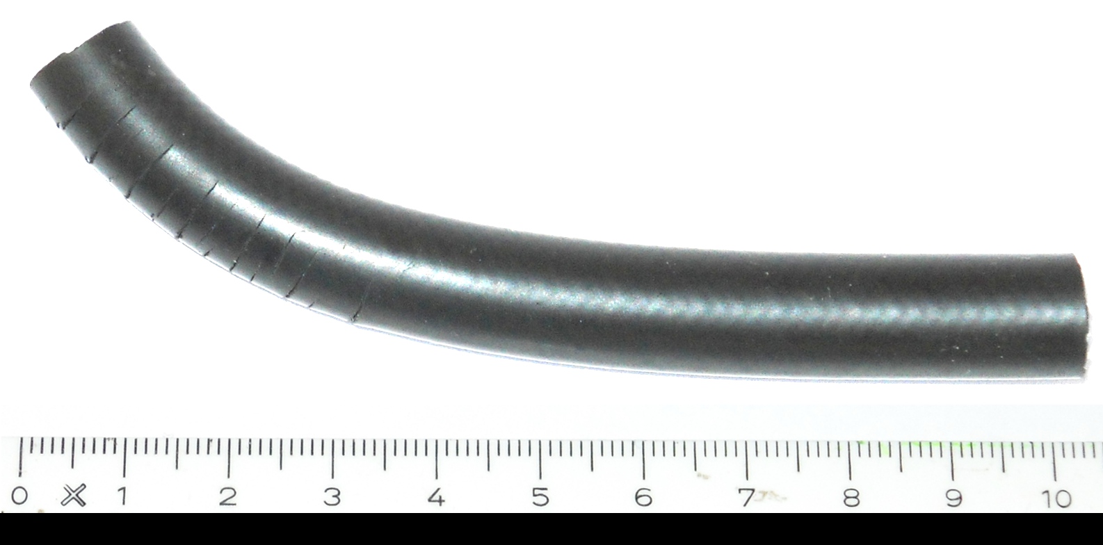
- Quick-Fit Coupling are a critical point regarding reliability. Water pressure drop of these devices are generally low. See example on 1/4" solution being measured .png.
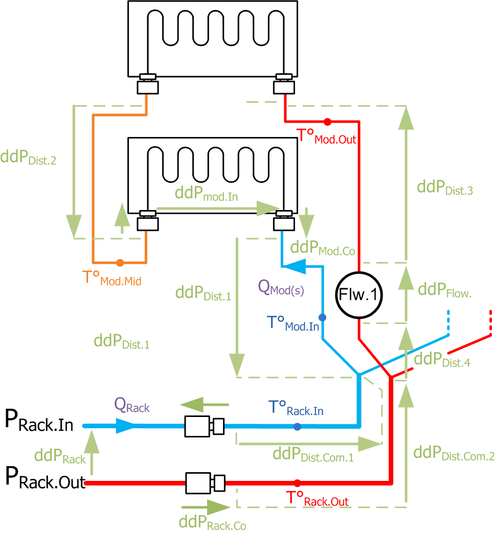
Example of a Rack Internal distribution: 2 paths - 2 Modules in series .vsd
M/F Genre & Color Convention
- Rack General Water Layout Input & Output: flexible hoses terminated by Female water Connector for both.
Goal is to protect rack water connectors (transport), female connector assumed to be less fragile. - Power Module Water Layout Input & Output: Male water Connectors for both.
Male connectors on removable power module so that flexible hose attached to the rack are then also terminated by female connector.
Coupling connexion is assumed to be more handy when plugging the female part in a "static" male part. - Input Connector/Connexion = Blue
Water leaving the module is generally hotter than when entering it (cold=blue). - Output Connector/Connexion = Red
Water leaving the module is generally hotter (red=hot) than when entering it.
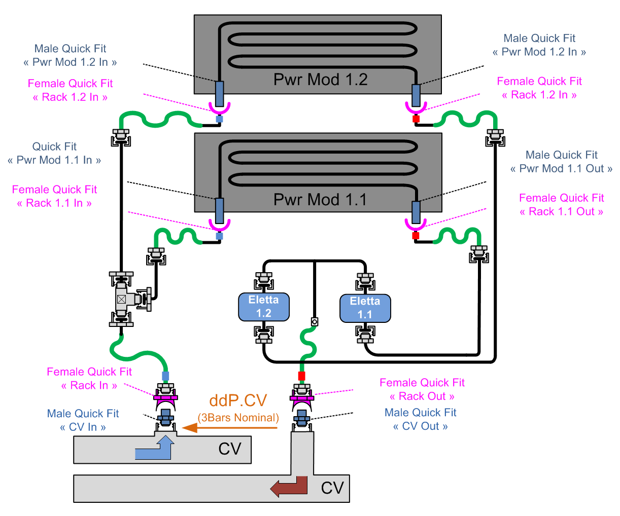
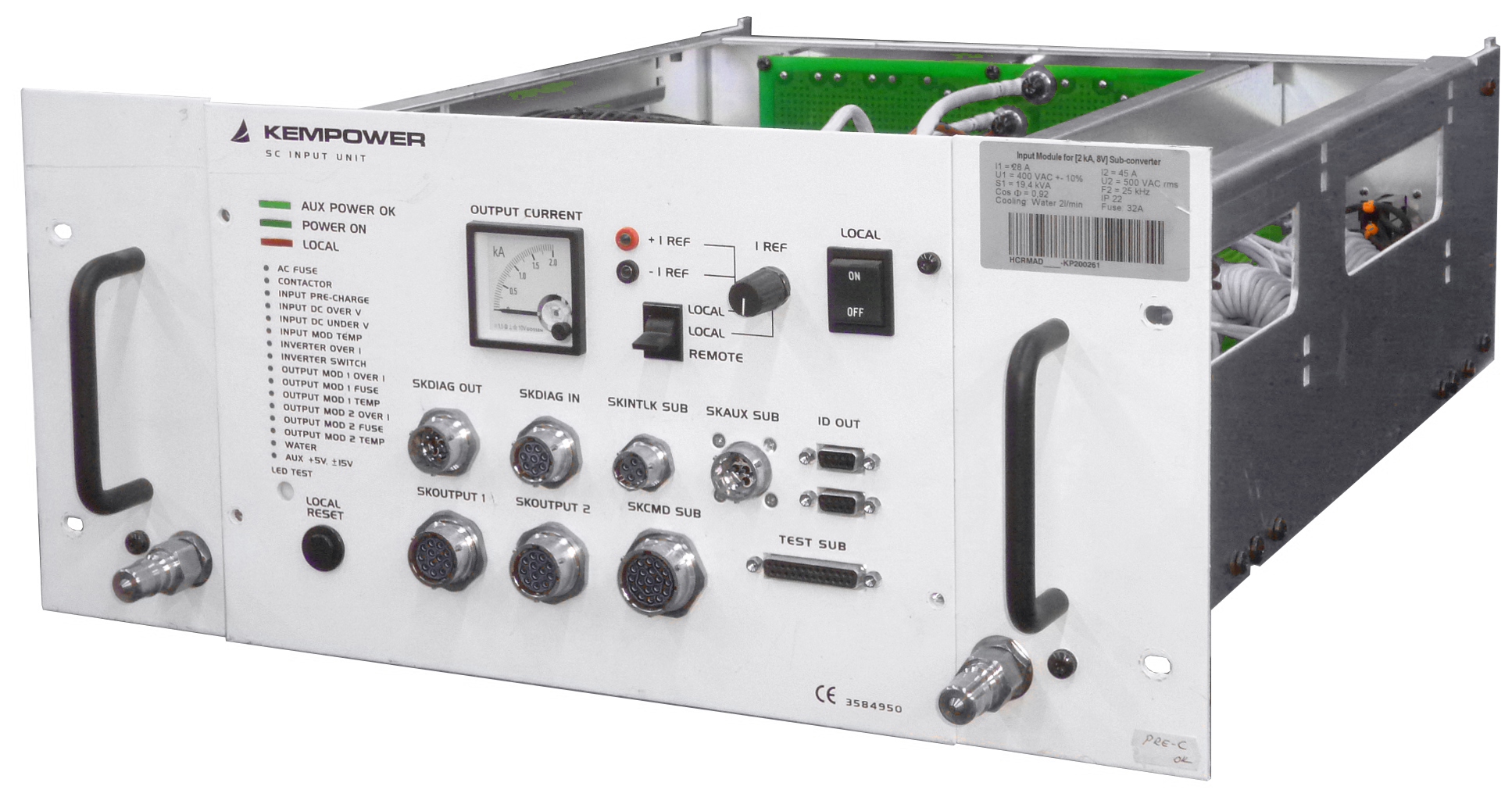
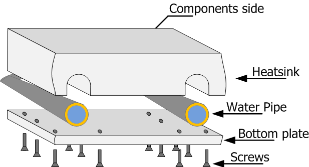
Example of a M/F convention application and a Power Module realization example
Installation Rules
Thermal Design
Water flow requirements:
E=m.C.dT (E=Energie [J], m=weight [kg], C=chaleur massique [J/(°C.kg)], dT=Temperature difference [°C])
This formula applied to a flowrate gives the following formula:
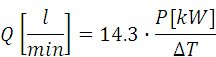
Formula-1: Water Flow vs Power vehiculated in water & its temperature rise
Designing a thermally effective transfer:
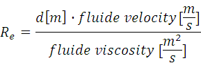
Formula-2: Reynolds number calculation
Formula which required the calculation of the fluide velocity![]()
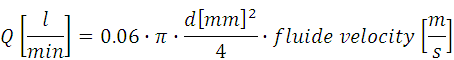
Formula-3: fluide velocity calculation
Leading then to the simplified formula (water @ 40°C) for the calculation Reynolds![]()
Formula-4: Reynolds number simplified calculation with 35°C water dynamic viscosity : 0,7.10E-4 Pa.s, and then a fluid viscosity of 7E-7 m²/s
Leading finally to the very handy formula (water @ 40°C) for achieving a efficient thermal cooling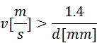
Formula-5: Efficient cooling conditions (water @ 40°C)
On the other hand, excessive water speed my cause erosion corrosion of the cooling pipe: in copper this starts taking place at velocity > 3m/s. This is one of the reasons why efficient cooling in small pipes always produces some erosion.To find the good combination of diameter and water velocity for a given flow this condition shall be iterated with:
Formula-6: Efficient cooling conditions (water @ 40°C)
Calculation of the pressure drop:
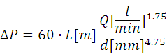
Formula-7: Estimation of a given layout water pressure drop
Validation of reliable design
P.transmitted < 8 Watts / cm2 (above 50 Watts / cm2, the conditions are very challenging and would likely lead to material destruction).
Validation
PED (Pressure Equipment Directive)
IEC62477-1 requirements:
For routine tests, the pressure shall be increased to the maximum pressure rating of the system. The pressure shall be maintained for at least one minute. There shall be no thermal, shock, or other hazard resulting from the test. There shall be no leakage of coolant or loss of pressure during the test, other than from a pressure relief mechanism during a type test.
For both type and routine test, the pressure shall be maintained for at least one minute.There shall be no thermal, shock, or other hazard resulting from the test. There shall be no leakage of coolant or loss of pressure during the test.
CERN requirements:
LPC water cooled converters shall respect:
- A type test with pressure increasing at a gradual rate until a pressure of 24 bars is achieved and maintained for at least one minute;
- Routine tests, with pressure increased up to 24 bars and maintained for at least one minute.
Marking
- Production Year;
- Equipement Absolute pressure [1; 16] bars.
Example

| TOP | CHARTE | HTML | CSS | Ver : 21-02-2024 09:52:31 | Webmaster : Michel GEORGES. |