|
RPLB/BA/BB / LHC120A-10V |

|
 |
|
 |
|
 |
CERN
|
SY
|
SY-EPC
|
EDMS
|
PROJECTS
|
ODF
/
OOXML
|
|
CERN
|
SY
|
SY-EPC
|
EDMS
|
PROJECTS
|
ODF
/
OOXML
|

|
|
|
|||||||||||||||||||||||||||||||||||||||||||||||||||||||||||||||||||||||||||||||||||||||||||||||||||||||||||||||||||||||||||||||||||||||||||||
| Power In | 3 ~ 230V/3A |
| Power Out | +/- 120A +/-10V |
| Converter Type | 4 Quadrant |
| Control type | FGC2 / WorldFip |
| Current Accuracy | 50 ppm@ 30 mn |
| 100 ppm@ 24 h | |
| 1000 ppm@ 1 year | |
| (1 ppm=120uA=0.12mA) |
 Design & Operation Responsibles
| 1st Intervention |
 Piquet SY-EPC LHC
|
| Responsibles: |
 Yves THUREL
|
 Benoit FAVRE
|
|
|
|
Power Converter Architecture
This Power Converter is used in LHC Machine to power superconductive magnets. It is located in the LHC underground installation, close to the loads to limit cable losses in the underground installation.
Different parts were designed and produced separately, Power Converter being finally integrated in a housing rack, with 3 main parts:
- High Precision Current sensors: DCCTs, able to measure DC current at the required precision.
- Power Part: Power Rack and its removable Power Module
- A Digital Controller (FGC) using WorldFip bus in charge of:
- The high level control from and to the Cern Control Room
- The high precision digital current loop
- Collecting and reporting all status, faults, and measurements from all the different parts to the remote services, for diagnostic and operation purposes.
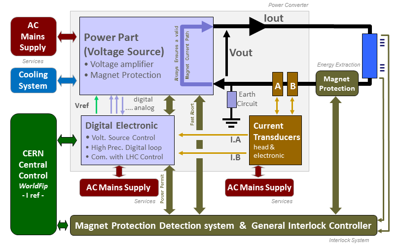
Power Converter simplified Architecture .ppt
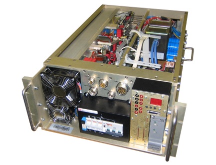
Power Part
Voltage Source is based on a full bridge phase shifted topology followed by a 4 quadrant linear stage to allow the 4 quadrant operation. This topology gives a very low output EMC noise, at a cost of complexity with regards to the 4 quadrant linear stage, combining main regulation loop + circulating current loop, being powered by a DC-DC controlled by another loop.
Both DCCTs used for the high precision current loop (FGC) are located directly in the voltage source, even if not used by it to operate as a pure voltage source.
A 19'' rack provides connectivity from AC network and to the load, housing up to 4 Voltage Source Power Modules.
| Power Converter | Power In: 3 ~ 230V/3A |
| Power Out: +/- 120A +/-10V | |
| Cooling type: Fans | |
| Power Racks | weight: 186 kgRack.4x / 150 kgRack.2x (Power Modules and full equipped electronic chassis excluded) |
| width: 600 mm (19"-rack) | |
| depth: 900 mm | |
| height: 2050 mm (DC busbar Holes: 2025 mm) | |
| Power Module | weight: 47 kg |
| width: 480 mm (19"-rack-compatible) | |
| depth: 730 mm | |
| height: 223 mm(5U) | |
| Rack Elements | Electronic Chassis ..... 11 kg (Fan Tray + Chassis + 2x FGCs + 2x PSUs + AC-DC) |
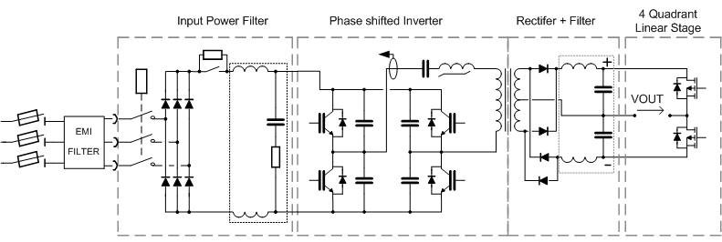
Power Part simplified Architecture / Topology .vsd
Typical Curves
| Output Voltage High Freq. Ripple / Current .txt | [ 0A 0V ] V 150MHz: 10us / 2ms - 30MHz: 2ms / 2ms - I IAB: std FFT |
| [ 60A 4.5V ] V 150MHz: 2ms / 10u - 30MHz: 2ms / 2ms - I IAB: std FFT | |
| [120A 9.2V] V 150MHz: 2ms / 10u - 30MHz: 2ms / 2ms - I IAB: std FFT | |
| Output Med. Freq. Voltage Ripple < 100 kHz .txt | [ 0A 0V ] V 100kHz: 2ms |
| [ 60A 2.0V ] V 100kHz: 2ms | |
| [120A 4.0V] V 100kHz: 2ms | |
| Output Low Freq. Voltage Ripple < 1 kHz .txt | [ 0A 0V ] V 1kHz: 400ms |
| [ 60A 2.0V ] V 1kHz: 400ms | |
| [120A 4.0V] V 1kHz: 400ms | |
| Output Voltage Large Signal Limitations.txt | [1Vpp, 10Vpp]Square - [10Vpp]Triangular - [10Vpp]Sinus |
| 0V distortion crossing | 0A |
| Inverter Current .txt | [0A 0V] @50kHz [120A 4V] @70kHz [120A 10V] @50kHz @70kHz |
| Output Power Rectifier Voltage (induct. snubber) | [0A 0V] +detail, [60A 5V]+detail, [120A 10V] +detail |
| Output Power Rectifier Voltage (non-inductive snubber) | [0A 0V] +detail, [120A 10V] +detail |
| Inverter Full-Bridge IGBT Volt.(VCE / 1200V) | [0A 0V], [120A 10V] |
| 4QLS Output Voltage rejection Measurments .txt | Complete Measurement Report .pdf |
| EMC AC Side Perturbations Meas. Cond. | 0A, 120A |
| Earth to DC Output +/- Polarities Voltage | [ xA xV ] DC NEG: 150MHz 2ms |
| [ 0A 0V ] AC NEG: 150MHz: 10us / 2ms / 2ms - 30MHz: 2ms / AC POS: | |
| [ 60A 4.1V] AC NEG: 150MHz: 4us / 10us / 2ms - 30MHz: 2ms / AC POS: 4us | |
| [120A 9.2V] AC NEG: 150MHz: 4us / 2ms / 2ms - 30MHz: 2ms / AC POS: 4us | |
| Earth to DC Neg Pol. FFT | 0A, 120A |
| Earth Leakage Current Meas. Cond. | I.Earthstatistical-on-300x |
| Starting Sequence Vin.DC | Vin.DC |
| Voltage source Step Resp. crossing quadrant | Step Voltage Response vs Quadrant Type |
| Voltage source bandwidth Vout/Vref | Voltage Bandwidth |
| Voltage Source Efficiency vs Output Power | Efficiency Graph |
Control Part
Control & regulation principles are summarized in a detailled schematics representating only the part involved in the output current regulation scheme.
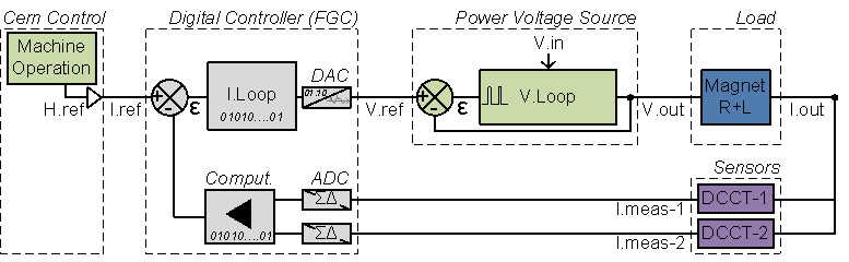
Regulation Control simplified schematic .vsd
High precision current control loop is managed by the digital controller called FGC (Function Generator Controller). This unit includes a high precision Sigma Delta Analog to Digital Converter which digitalize the analog current measurement coming from 2 DCCTs (DC current Transducer). Precision is then directly relying on sensor precision: DCCT, the ADCs, and the algorithm being used for the regulation loop. Voltage source is then used as a power amplifier, powering the load through a high bandwidth voltage loop (>500Hz).
Magnet Protection
Power Converter is part of magnet protection scheme, even if not directly fully responsible of the monitoring, diagnostic of the superconductive magnet status and the magnet energy discharge. Dedicated systems QPS (Quench Protection System) + PIC (Power Interlock Controller) can interlock Power Converter if magnet safety requires it.
In LHC, only RCO circuits are using the Fast Abort Power Module interlock. LHC120A-10V magnet (except RCO ones) are indeed considered as safe per design and can handle their own energy without external energy extraction system. Converter then detects a quench when occuring through the magnet impedance growing (resistance) up to a point Power Converter cannot regulate anymore.
LHC120A-10V Power Converter is also responsible of the current leads protection. These current leads are the 2 (minus and plus polarities) electrical conductors located at the transition between cold and warm environment.
Power Converter is expected to:
- Always ensure that external protection system can stop the Power Converter.
Power Converter provide a safe incoming signal called Fast Abort. This redundant signal uses 2 paths to interlock and stop the converter and its redundancy is checked each time it acts. - Stop powering the load always providing a safe path for magnet current.
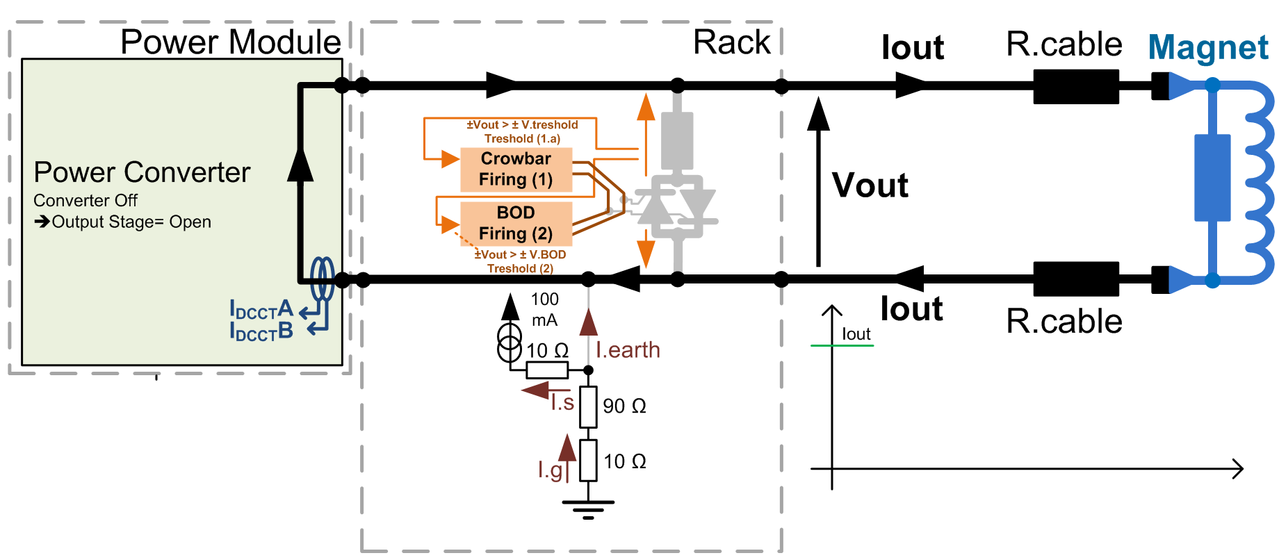
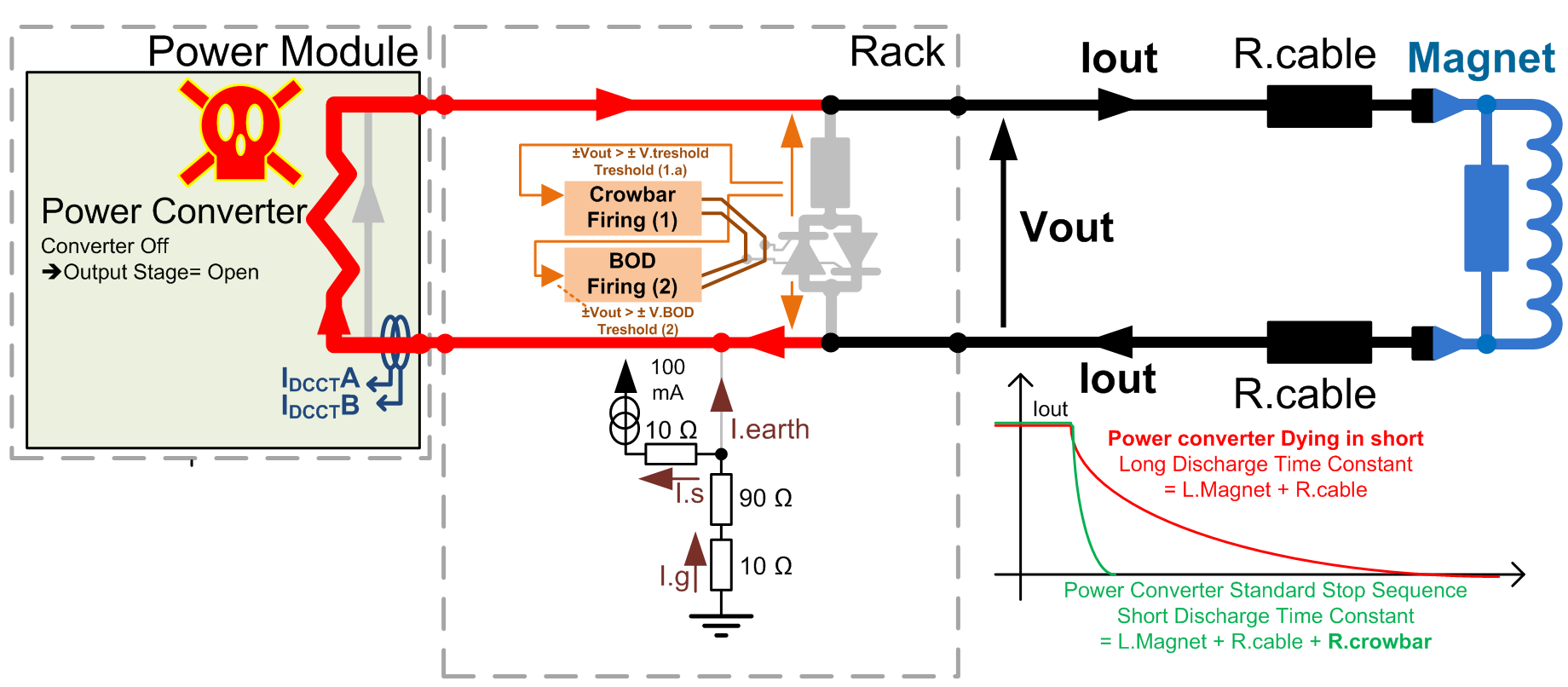
Magnet current path is ensured through a dedicated system called crowbar or through Power Module in case its output stage dies in short. Crowbar active system is located in the rack and provides a safe resistive discharge path for magnet current, with a capability to dissipate, most of the time, part of magnet energy. - Monitor Earth current of the total circuit and take the right action if threshold reached.
Total circuit = converter + load (magnet and its DC cables). - Monitor the voltage across the 2 current leads, and take the right action if threshold reached .
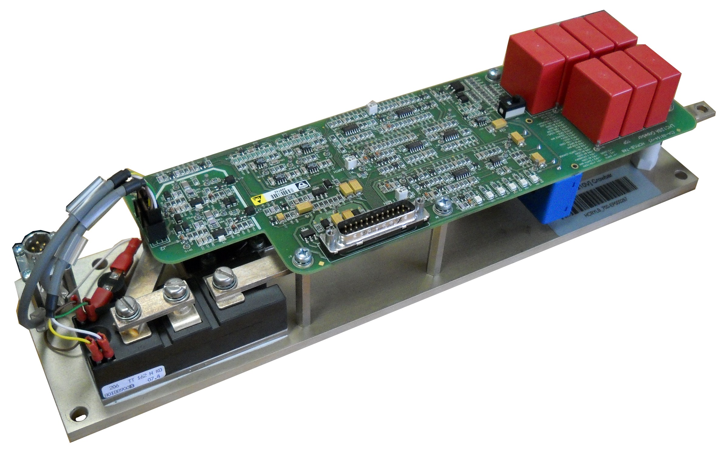
- Crowbar
The system is based on a 80 mOhms Power Resistance (made of 6x 200 W HXP200 0.47 Ohms 5% Power resistors) series 2x back-to-back thyristors (TT142N12KOF, [142 A; 1200 V] ) being fired at a given output voltage (\B113V), and then providing a safe path for magnet current. Energy crowbar can handle is based on 5.27H 5mOhms magnet @ 77A, which represents a total and maximum crowbar energy of 12kJ (3kJ absorbed by cables). One should never forget a Power Module dying with its output stage in short will prevent the crowbar from dissipating magnet energy. No DC contactor in series is provided to ensure this Power Module case dangerous failure, regarding magnet energy discharge.
 No fault
-
converter → OFF
-
Crowbar Fully Active
-
Worst Case (Power Module Crash)
No fault
-
converter → OFF
-
Crowbar Fully Active
-
Worst Case (Power Module Crash)
Crowbar System simplified schematic .vsd
- Fast Abort Interface
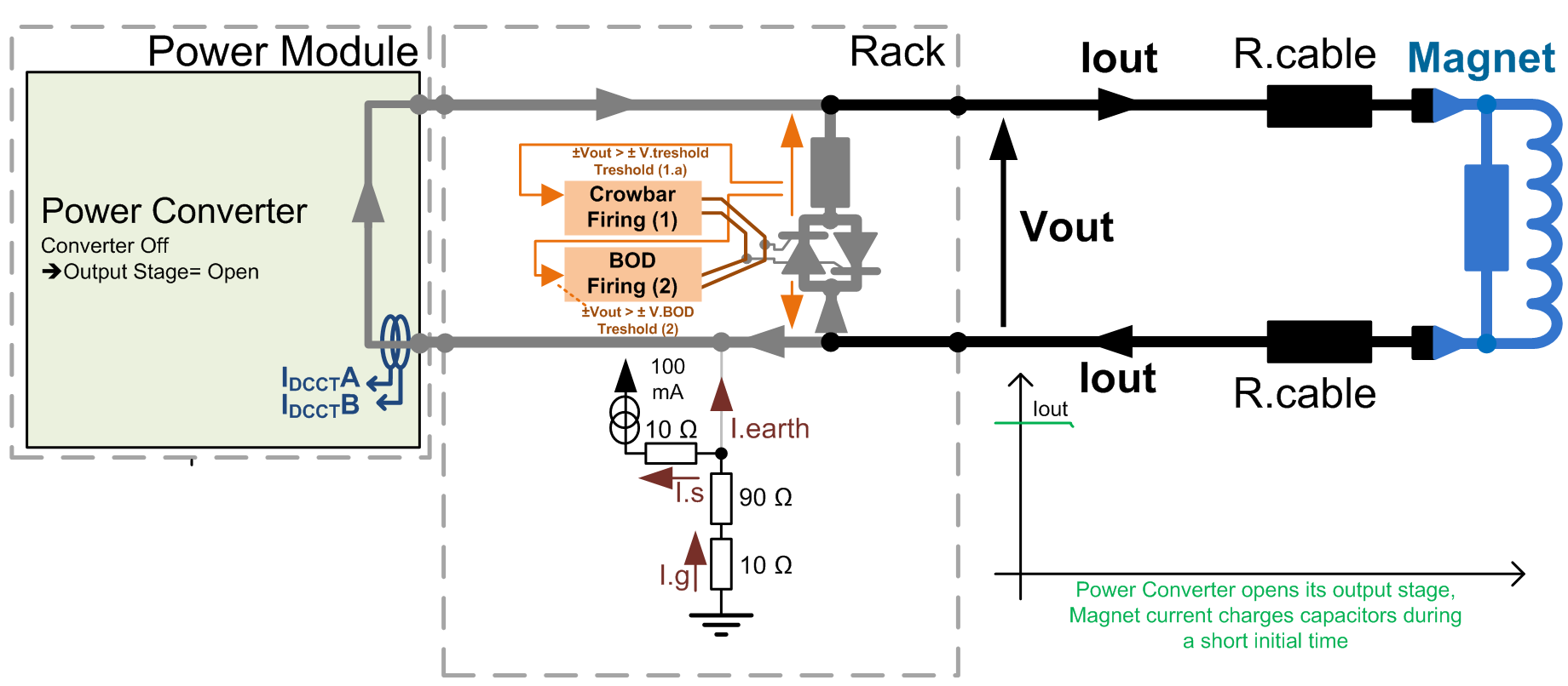
Machine Interlock system can request a Fast Abort to the converter, in case a quench is detected. Converter is then assumed to react as soon and as quick as possible, stopping providing energy to the load. Delay time between a Fast Abort request and actual opening of the 4-quadrant output power stage is less than 1mS, but 20ms, AC Mains Contactor delay time, should be considered as a worst case (internal control malfunction case). A typical sequence could be described as follow:
- t=[=0 ms] → Fast Abort Request from Machine Interlock
- t=[=1 ms] → Power Converter Output Stage opens and becomes not conductive
In case Power Module died with output stage in short, 1ms > 20ms (contactor delay)
- t=[>x ms] → Load energy is transfered to crowbar up to V.crowbar = 13V.
Capacitor charge depends on initial load current (I=C.dV/dt).
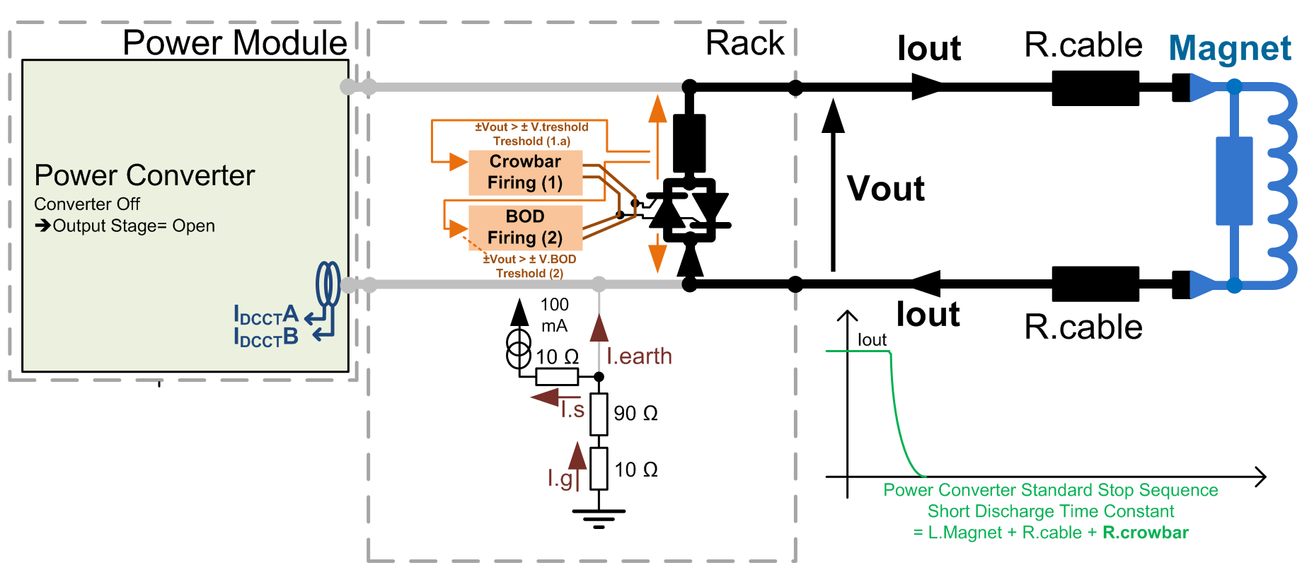
C.to.be.considered=C.Crowbar//C.Power-Module - t=[=y ms] → Crowbar Thyrsitor is fired, absorbing Crowbar capacitor + Load energy.
An initial over-current generally happens at initial thyristor start-up. - t=[> end] → Load energy starts to be dissipated in various resistances.
R.to.be.considered=(R.crowbar + Thyristor) + (R.cable) + (REE) + (R.quench).
This signal being part of the magnet safety scheme, it is acting redundantely at the level of Converter AC Mains Contactor. 2 paths are used and monitored to stop the contactor.
A possible schematic is described below: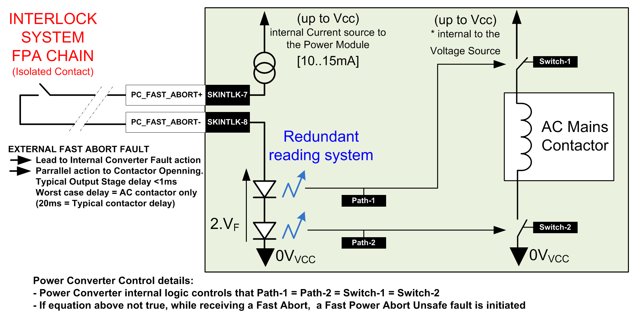
Fast Abort System simplified schematic .vsd
- Earth System
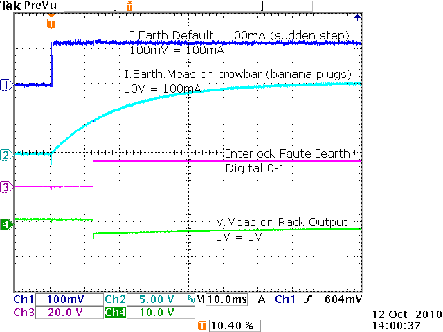
Detection system is an active system, since relying on a 100mA current source powering a 100Ohms resistor connected between earth and negative polarity of the Power Converter. A common mode voltage is then created, (100mA x 100Ohms) making possible to detect an earth fault even with converter being OFF. (OFF, not condamned).
Earth system proposed in this converter is not capable to handle a high common mode voltage potentially created by a series-to-the-load-type discharge system, in case of a double earth fault.
Earth fault current is filtered at the level of the crowbar (1st order@ 8Hz), and a strong earth fault will make the converter trip 20ms after it happens. See this real measurement curves .png.
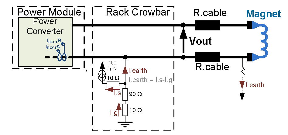
Earthing System simplified schematic .vsd
- Current Leads Protection
These current leads are protected monitoring the voltage across them. Per design these current leads must not developp more than 150mV at full current. Such a case would mean their thermal stabilization is not correct.
Design is simply facing some common mode voltage coming from Earthing system added from the differential voltage, when trying to measure a small voltage of some mV across long distances.
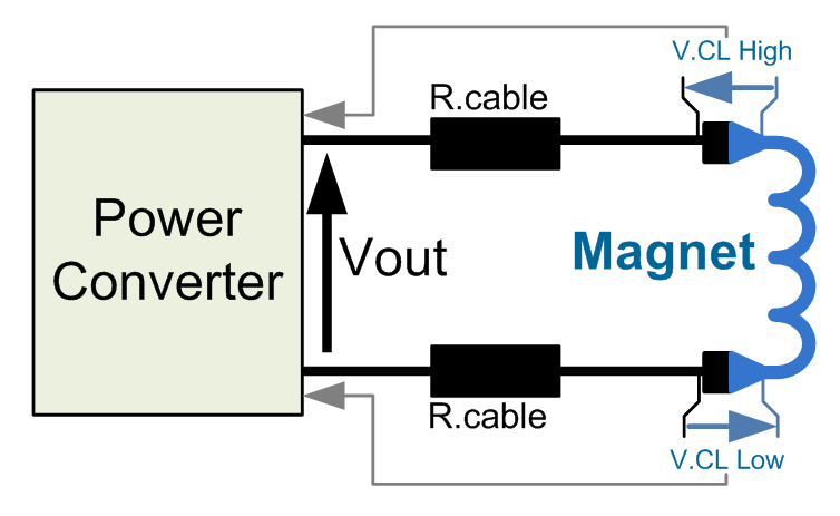
Current Leads Protection System simplified schematic .vsd
Power Converter Components
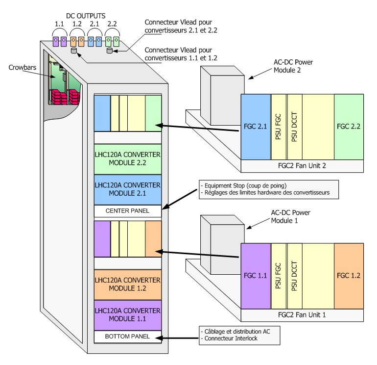
A power converter is actually a sum of different equipments under several different sections in the SY-EPC group. The modularity is a key factor for easier maintenance with regards to LHC tunnel access conditions.
Power Converter Rack can accept up to 4 Power Converters. Electronic Chassis, fan tray unit and AC-DC Power Module are shared 2x2 in such a case.
- Power Converter Rack
- Power Module
- FGC2 Fan tray unit
- Rack Crowbar
- Electronic Chassis (Type 1) .edms
- Digital Controller: FGC2
- AC/DC Power Module
- PSU FGC Tri-volt
- PSU DCCT Bi-volt
Magnet Types
| Orbital corector | QSKxxx |
Machine Installation
| Air losses | Full Rack [4x] @ P.nom (incl. FGCs) | 2450 Watts |
| Full Rack [2x] @ P.nom (incl. FGCs) | 1200 Watts | |
| P.losses [W] = n*[1200*(1/0.72-1)] + n/2*300. | ||
| LHC Use | 290 Power Converters (16 RCO types, 274 standard 120A) | |
| Radiation Safe Locations (183) | UA23 (21), UA27 (29), UA43 (06), UA47 (06),
UA63 (12), UA67 (12), UA83 (21), UA87 (21), UJ23 (08), USC55 (05), UJ33 (10), UJ43 (08), UJ47 (08), UJ83 (08), UJ87 (08) |
|
| Radiation Mitigated Locations (15) | UL14 (05), UL16 (05), UL557 (05) | |
| Radiation Exposed Locations (92) | RR13 (18), RR17 (18), RR53 (18), RR57 (18),
RR73 (10), RR77 (10), |
Production Contract & Contact History
| Developped | CERN AB-PO-SC |
| 2001-2005 | |
|
Yves THUREL
|
|
 David NISBET
|
|
|
Benoit FAVRE
|
|
| Manufactured | Portugal |
| EFACEC | |
| Production | 343 Pc |
Converter Circuit Names
| TOP | CHARTE | HTML | CSS | Ver : 04-09-2023 17:12:54 | Webmaster : Michel GEORGES. |