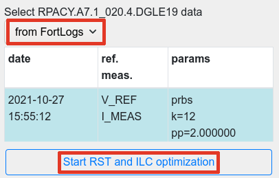
|
fresco |

|
|
|
|
 |
|
 |
|
 |
CERN
|
SY-EPC
|
EDMS
|
PROJECTS
|
ODF
/
OOXML
|
|
CERN
|
SY-EPC
|
EDMS
|
PROJECTS
|
ODF
/
OOXML
|

|
|
|
||||||||||||||||||||||
| Set your converter at current of interest |

|
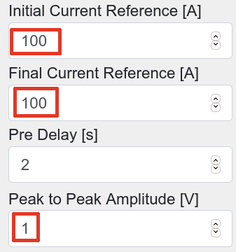
Converter can be set in V or I reg.mode, before PRBS or Sinefit identification, both performed in voltage mode. |
|---|---|---|
| Launch Fresco, select your device & open PRBS Tab |
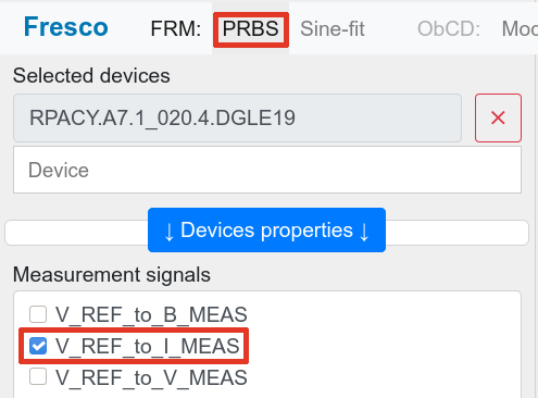
|
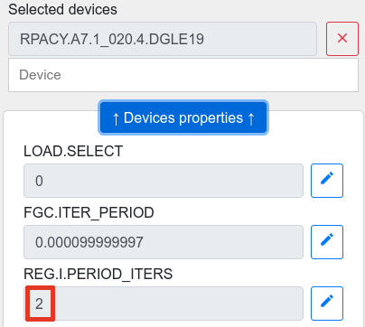
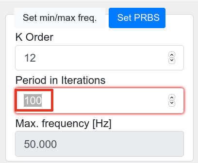
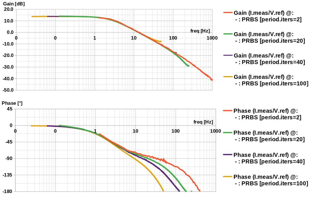
Identify the system being controlled by the FGC: Imeas=f(Vref), including load and converter, using PRBS and correct period iteration = reg.i.period_iters. It is only required to identify the system where the closed loop is expected (no need to get all low freq. poles). Period iteration is limited to 10. For a reg.i.period_iter of 20 or more, use Period iterations = 10. The regulator synthesis will adjust the phase automatically. |
| Impact of period.div on system identification |
|
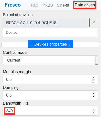
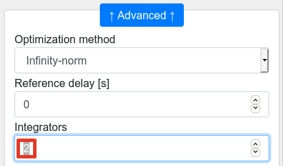
Data driven step which follows relies on discrete system being evaluated. If the gain is unchanged, phase includes the delay from system discretisation. It is then required to use the correct period iteration number included in the data being proposed to the automatic optimization. 
|
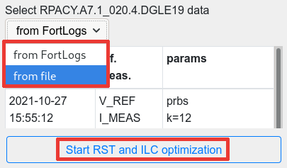
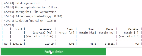
 Process with regulator optimization
 Evaluate regulator performance & push to FGC
 Measuring real system performances
| Use PowerSpy |
|
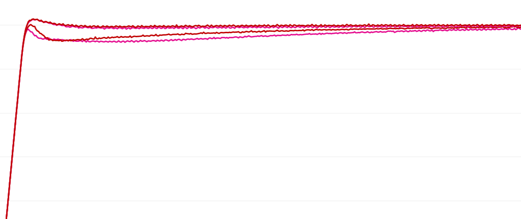
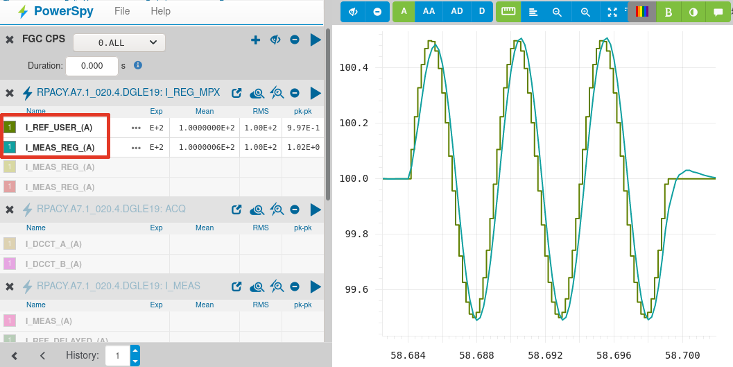
User PowerSpy to measure performance, directly on signals of interest I_MEAS_REG & I_REF_USER, found in I_REF_MPX Powerspy logs, and using error signal as well I_ERR_(A). |
|---|---|---|

|
To select them, if not shown per default, please choose I_REF_MPX channel. | |

|
Open selection pane. | |
 |
Fetch signals and replace them. | |
| Use FGCRun+ |

|
- g meas.i.max_abs_err zero. - s ref sine,App,nb,per. or - s ref square,Astep,nb,per. - s ref.run - g meas.i.max_abs_err. |
| TOP | CHARTE | HTML | CSS | Ver : 19-02-2022 13:16:30 | Webmaster : Michel GEORGES. |

