|
Converter-Concepts / EMC |

|
 |
|
 |
|
 |
CERN
|
SY
|
SY-EPC
|
EDMS
|
PROJECTS
|
ODF
/
OOXML
|
|
CERN
|
SY
|
SY-EPC
|
EDMS
|
PROJECTS
|
ODF
/
OOXML
|

|
|

|
||||||||||||||||||||||||||||||||||||||||||||||||||||||||||||||||||||||||||||||||
| Meas Type | Differential Noise | Dissymmetrical Noise |
| Frequency Domain | Validation Criteria: → See Gabarit/Levels below |
|
| Time Domain | Validation Criteria: → No measurement required on time domain |
|
Recommended measurement methods vs frequency range
CERN Frequency Reference Gabarit/Levels
- [2kHz..10kHz] range is out of standard EMC equipement range (impedance and measurement capability) and should be treated following CERN recommandations.
- Quasi-Peak Measurement required, even if peak could be used (saving time) initially to point at possible issues to be later studied more carefully. A Peak measurement below limit confirms entirely the compliance with Quasi-Peak limit. The more noise signal "duty cycle" reduces (its frequency of apparition) the more Quasi-Peak Measurement result differs strongly from Peak one. Converter noise (by nature) typically generates less than 6dB of difference between Q-Peak and Peak.
Using
![]() CERN level
-
CERN level
-
![]() CERN level vs CISPR11
-
CERN level vs CISPR11
-
![]()
Frequency Domain measurement Test Set Up .vsd
CERN Input Side Gabarit .xls
Predefined Plot versus standards .xls
| Frequency Range | [9kHz..150kHz] | [150kHz..30MHz] | [30MHz..300MHz] |
| Resolution Bandwidth | 200 Hz | 9 kHz | 120 kHz |
Resolution Bandwidth to be set on Spectrum Analyser vs frequency range
Measurement method
- LISN provides "dyssimmetrical" measurement, from ground to active measured lines, getting common and differential mode.
- LISN provides known & balanced impedance (50 Ohms line to ground f>fo) on all lines (3x for 3-phases) giving meas. reproducibility.
- LISN provides also reduction of existing noise on power network not to pollute the measurements.
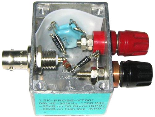
- A 1500 Ohms EMC probe measurement is possible when LISN is not available ...
- A frequency domain measurement can be done using modern oscilloscope ...
| Meas. / Freq. | [2kHz..9kHz] | [9kHz..30MHz] |
| Frequency Domain | Oscilloscope + FFT Module + Single-Ended Probe → to cope with range of [2kHz..9kHz] |
Spectrum Analyser + LISN |
| Spectrum Analyser + Standard 1500 Ohms Probe → Accepted if input current too high for standard LISN |
Recommended & practical measurement methods vs frequency range
Using
![]() LISN
-
LISN
-
![]() 1500 Ohms Probe
-
1500 Ohms Probe
-
![]() Oscillo + Single-Ended Probe
Oscillo + Single-Ended Probe
Frequency Domain measurement Test Set Up .vsd
 Output Side: Conducted Noise
CERN Compliance Matrix
CERN pay high attention to noise below 1MHz, especially in differential mode, even if randomly distributed and with very low ocurrence, or coming from specific conditions: 0V crossing in 4 quadrant power converters, a fan or contactor switched on... For this reason, time-domain measurement are required, in addition to frequency-domain measurement, to catch these unexpected signals.
| Meas Type | Differential Noise | Dissymmetrical Noise |
| Frequency Domain | Validation Criteria: → See Gabarit/Levels below |
|
| Time Domain | Validation Criteria: Trigger set @ V.treshold (150mVpk if Vout < 50V) → No trig expected after 10 sec, in any operating conditions (static or dynamic) |
|
Recommended & practical measurement methods vs frequency range
CERN Reference Gabarit/Levels
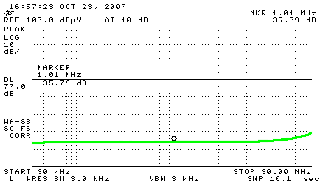
- [10Hz..10kHz] range is out of standard EMC equipement range (impedance and measurement capability) and should be treated with adequate material (bandwidth issue on 1500 Ohms probe for example, with a 35dB rejection for frequency higher than 10kHz usually).
- A time domain reference level Vpeak-peak measured with 100 MHz bandwidth capability should always be performed in parallel to this test.
- Reference gabarit is given (strong line) for a DC output voltage of less than 50V. Dashed line shows an hypothetic level for a higher range / purpose / topology application. This limit level is defined from final user requirements.
Measurement
Using
![]() Peak
-
Peak
-
![]() Quasi-Peak
Quasi-Peak
CERN Output Side Gabarit Peak-preferred (<50V dc output) .xls
Values for spectrum analyser are given below.| Frequency Range | [9kHz..150kHz] | [150kHz..30MHz] | [30MHz..300MHz] |
| Resolution Bandwidth | 200 Hz | 9 kHz | 120 kHz |
Resolution Bandwidth to be set on Spectrum Analyser vs frequency range
Measurement method
Differential Mode Measurement
- Some spectrum analyser with differential input exists, but FFT module available with modern oscilloscope fits well the frequency range.
- Avoid using differential probes, with common mode rejection ration not sufficient when reaching high frequencies.
- Better use a batterry powered oscilloscope than a insulation transformer on AC powered oscilloscope. (coupling capacitor)
- Always keep in mind that an ultra-basic measurement with a Fluke voltmeter (Series 79 or similar), used in AC.mode gives you interesting indication expressed in true rms value, in the range [45; 1 0000] Hz, regarding the noise being measured.
Output differential mode measurement methods .vsd
| Meas. / Freq. | Vout | [10Hz..2kHz] | [2kHz..9kHz] | [9kHz..30MHz] |
| Frequency Domain | < 42VPeak | Battery Powered Oscilloscope + Single-ended Probe + Oscilloscope FFT Module |
||
| > 42VPeak | 100MHz Oscilloscope + FFT Module + 100MHz High CMRR / Bandwidth Differential Input Probe |
|||
| Time Domain |
NA | 100MHz Oscilloscope + 100MHz High CMRR / Bandwidth Differential Input Probe |
||
Recommended & practical measurement methods: frequency range vs Frequency / Time Domain
"Common Mode" or dyssimmetrical Measurement
- For practical reason, dyssimmetrical measurement on output side is done at the level of the standard DC connections (bolts), with ground reference connected locally to the busbar (30cm area). Electrical high frequency conductiviy of the rack is assumed compliant.
- Measurement has to be made on both polarities even if often identical (high frequency diff. capacitors usually being used).
- A 1500 Ohms EMC probe or a standard modern oscilloscope probe provide sufficient impedance and is not intrusive.
- A 1500 Ohms EMC probe measurement is possible when LISN is not available ...
- A frequency domain measurement can be done using modern oscilloscope ...
Using
![]() Oscilloscope
-
Oscilloscope
-
![]() Spectrum Analyser
Spectrum Analyser
Dyssimmetrical Measurement .vsd
| Meas. / Freq. | [10Hz..2kHz] | [2kHz..9kHz] | [9kHz..30MHz] | |
| Frequency Domain 2 possibilities accepted |
1 → | Oscilloscope + Single-ended Probe + FFT Module |
||
| 2 → | Oscilloscope + Single-ended Probe + FFT Module |
Spectrum Analyser + Standard 1500 Ohms Probe |
||
| Time Domain |
100MHz Oscilloscope + 100MHz Single-ended Probe |
|||
Recommended & practical measurement methods: frequency range vs Frequency / Time Domain
Measurements examples
| TOP | CHARTE | HTML | CSS | Ver : 18-12-2020 21:54:37 | Webmaster : Michel GEORGES. |


