|
HCRPAHX / RF-3kA |

|
 |
|
 |
|
 |
CERN
|
SY
|
SY-EPC
|
EDMS
|
PROJECTS
|
ODF
/
OOXML
|
|
CERN
|
SY
|
SY-EPC
|
EDMS
|
PROJECTS
|
ODF
/
OOXML
|

|
|
|
|||||||||||||||||||||||||||||||||||||||||||||
| Power In | 3 ~ 230 V/ xx A |
| Power Out | [3 kA; 25 V] |
| Converter Type | 1 Quadrant |
| Control type | FGC3 / Ethernet |
| Current Accuracy | Class-7: 1000 ppm |
| (1 ppm=3 mA) |
 Involved Peoples
 Louis DE MALLAC
|
|
 Daniel SOLANO
|
|
 Maxime SARDANO
|
Introduction
A new powering layout with individual powering of each cavity will allow a full operational flexibility and a new way of operating the PS RF 10 MHz system, withimproved longitudinal stability and beam quality. The new converters will be installed in existing building around the PS accelerator to minimize the length of the cables and to optimize the cost and efficiency. The RF3kA converters will have to supply simultaneously the coarse tuning and the fine tuning currents.
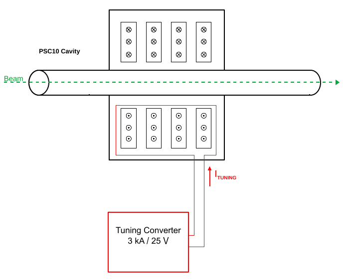
PSC10 circuit diagram .edms
Power Converter Architecture
Different parts were designed and produced separately, with the option of a Power Converter being finally integrated in a housing rack, with 3 main parts:
- Power Part:
- Power Rack (AC & DC distribution, interconnections)
- Ideally Removable Power Modules, including redundancy as much as possible.
- CERN Digital Controller (FGCx?):
- The high level control from and to the Cern Control Room (using fieldbus to be defined)
- The high precision digital current loop (when a voltage source is controlled)
- Collecting and reporting all status, faults, and measurements from all the different parts to the remote services, for diagnostic and operation purposes.
- High Precision Current sensor(s) (DCCTs)
- Measuring DC current at the required precision.
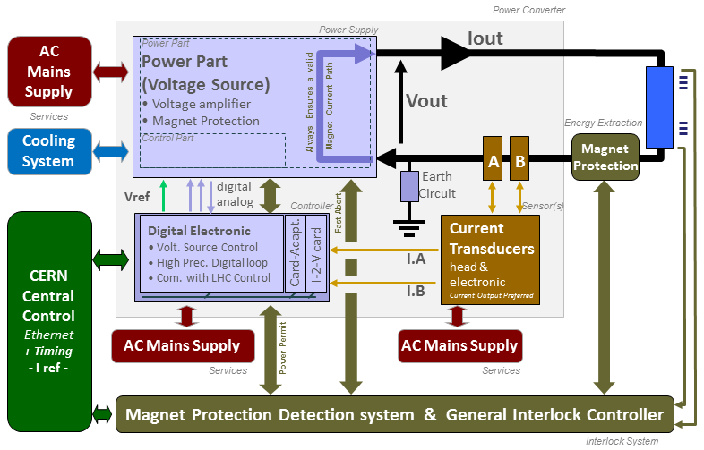
Power Converter simplified Architecture .ppt
Power Part
The proposed powering solution is based on twelve RF3kA power converters (eleven operational converters + one test converter). No additional spare converter is foreseen because only ten cavities are used for operation, i.e. one full RF system (cavity + converter) is available as a spare.
| Power In | 3 x 400V with Neutral / xxA |
| Power Out | 75 kW max (±3 kA ±25 V) |
| Cooling type | Water cooling and Fans |
| Converter Weight | Power Module ............ xx kg |
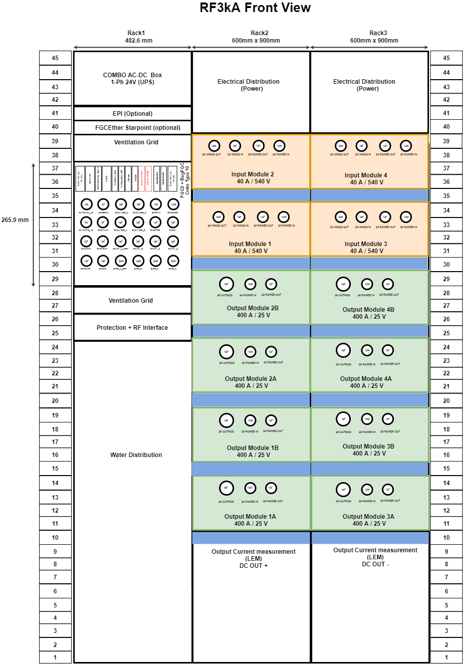
RF3kA converter racks .edms
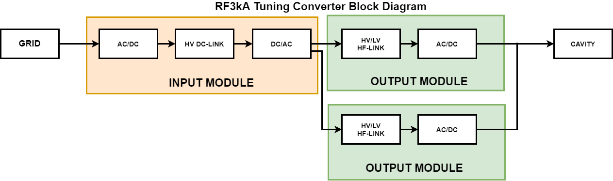
The RF3kA converter consists of one input module (rectifier + power filter + phase shifted inverter) and two output modules(HF transformer diodes rectifier + LC filter) connected in parallel as shown the diagram below.
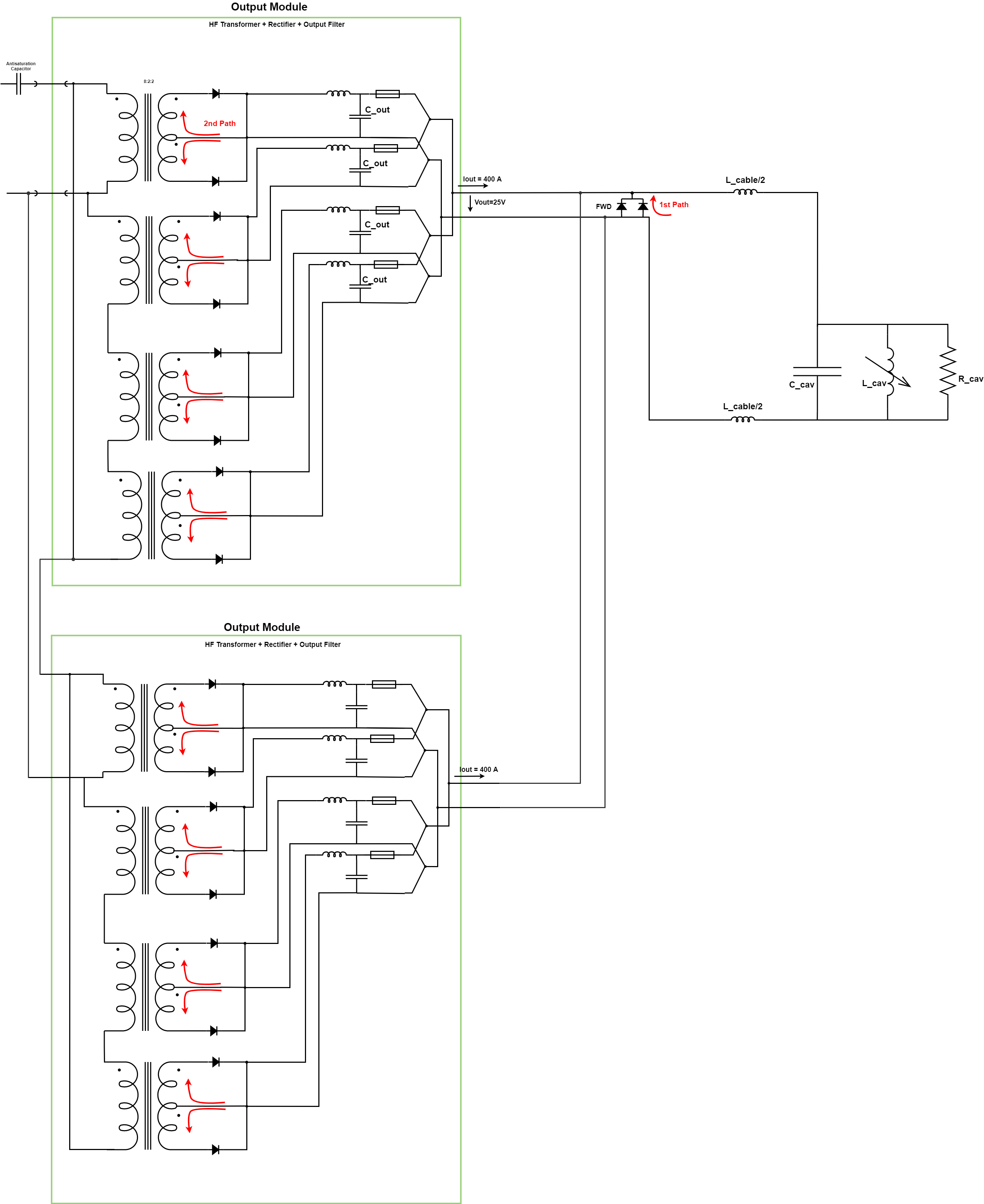
RF3kA schematic .edms
Typical Curves
| Output Voltage Ripple | TBD |
Control Part
Control & regulation principles are summarized in a detailled schematics representating only the part involved in the output current regulation scheme.
Control & regulation principles are summarized in a detailled schematic representating only the part involved in the output current regulation scheme.
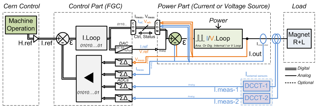
Regulation Control simplified schematic .vsd
High precision current control loop is managed by the digital controller called FGC (Function Generator Controller). This unit includes a high precision Sigma Delta Analog to Digital Converter which digitalize the analog current measurement coming from 1 or 2 Current sensors (DCCTs: DC current Transducer). Precision is then directly relying on sensor precision: current sensors, the ADCs, and the algorithm being used for the regulation loop. Voltage source is then used as a power amplifier, powering the load through a high bandwidth voltage loop.
Magnet Protection
Power Converter is part of magnet protection scheme, even if not directly fully responsible of the monitoring and diagnostic of the superconductive magnet status. Dedicated systems QPS (Quench Protection System) + PIC (Power Interlock Controller) can interlock Power Converter if magnet safety requires it.
Power Converter is then expected to:
- Always ensure that external protection system can stop the Power Converter through a safe signal called Fast Abort. This redundant signal uses 2 paths to interlock and stop the converter and its redundancy is checked each time it acts. It directly acts on DC Contactor bobbin, ensuring its opening as required.
- Stop powering the load in safe way (handling the magnet energy even when stopping, through dedicated system called free-wheeling diode). This passive system based on different paths using several free-wheeling diodes in the rack provide a safe discharge path for magnet current (energy).
- Monitor Earth current of the total circuit: converter + load (magnet and its DC cables), and take the right action if threshold reached.
- Fast Abort Interface
Machine Interlock system can request a Fast Abort to the converter, in case a quench is detected. Converter is then assumed to react as soon and as quick as possible, stopping providing energy to the load. This signal being part of the magnet safety scheme, it is acting redundantely at the level of Converter DC Mains Contactor. 2 paths are used and monitored to stop the contactor. The schematic is described below:
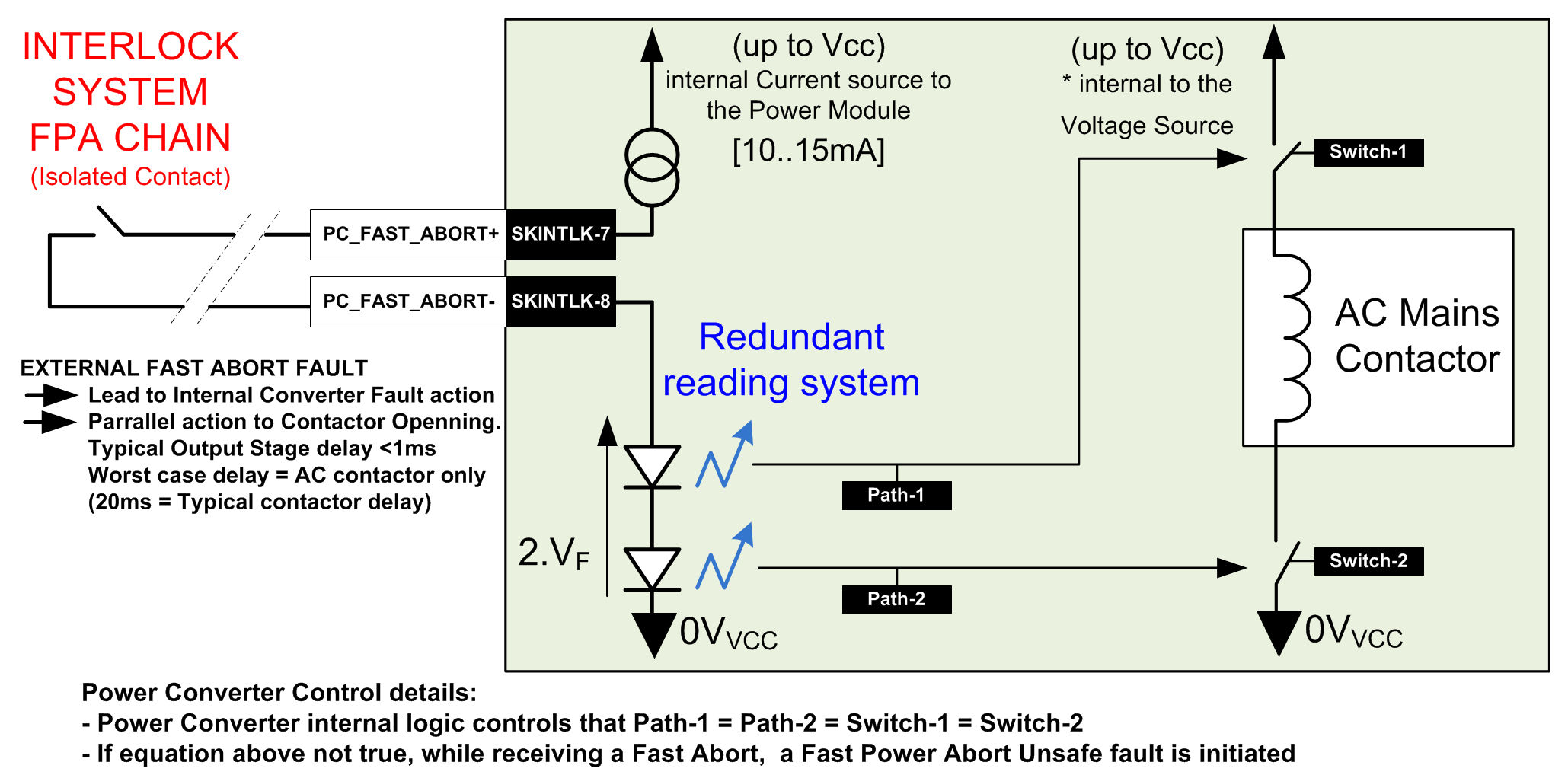
Fast Abort Interface .vsd
- Free-wheeling diode
The system is based on 3 different paths provided by Free-Wheeling Diodes providing a safe path for magnet current.
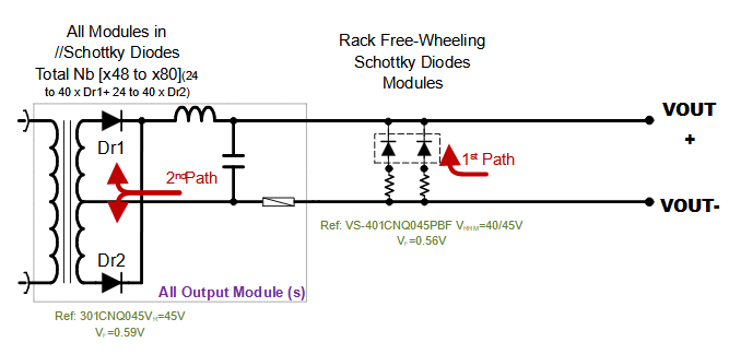
free-wheeling Diode System simplified schematic .vsd
- Earth System
This system is based on a two modes detection system: Active (by default) and Passive (configurable). In Active mode, the load is polarized to +10 V versus earth on its output mid-point (common mode). This allows detecting any earthing leakage faulty condition, without the need to energise the circuit for allowing the detection system to operate. A 100 Ohms earthing resistor in series with a 0.1 A fuse connects the mid-point to earth, with this resistance being used as a current sensor (shunt) sensing the circuit earthing leakage current. The system monitors the earthing leakage current to a value of 5 mA maximum allowed. The fuse (0.1 A fast) is provided to limit damage risk on the circuit side in any case and mode (active / passive).
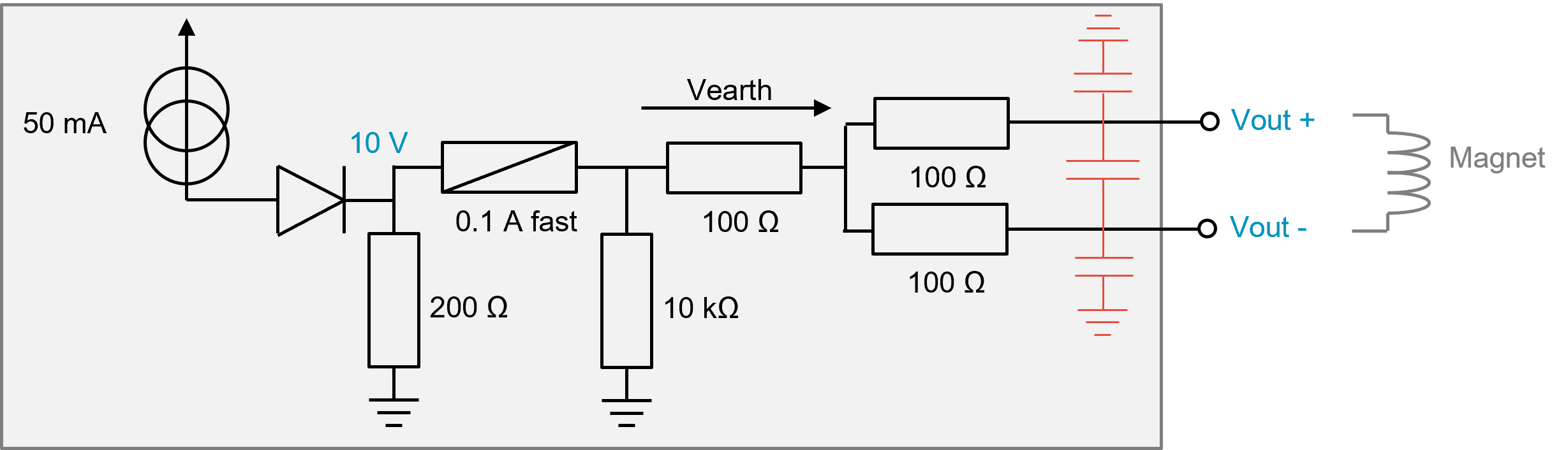
Earthing System simplified schematic .pptx
Power Converter Components
A power converter is actually a sum of different equipments under several different sections in the SY-EPC group. The modularity is a key factor for easier maintenance with regards to LHC tunnel access conditions.
Power Converter is built through two Power Racks. One contains the six Sub-Converter Power Modules, when the second one includes the converter crowbar and DC-contactor systems, the converter power part control electronic, the FGC complete Electronic Chassis, the two DCCTs head and their electronics.
Magnet Types
| to be defined | xxxxxx |
Machine Installation
| PS Use | xx Power Converters |
Production Contract & Contact History
| Developped | Designed/CERN |
| Manufactured | Contry(s) |
| Manufacture | |
| Production | xxx Pc |
| Responsibles: |
Converter Circuit Names
RPxxx
| TOP | CHARTE | HTML | CSS | Ver : 22-11-2022 10:47:18 | Webmaster : Michel GEORGES. |