|
RPAEO RF25kV |

|
 |
|
 |
|
 |
CERN
|
SY
|
SY-EPC
|
EDMS
|
PROJECTS
|
ODF
/
OOXML
|
|
CERN
|
SY
|
SY-EPC
|
EDMS
|
PROJECTS
|
ODF
/
OOXML
|

|
|
| |||||||||||||||||||||||||||||||||||||||||||||||||||||||||||||||||||||||||||
| Power In | 3 ~ 230 V / 400 A |
| Converter Type | 1 Quadrant |
| Control type | FGC3 / FGCEther |
| Voltage Accuracy | 1000 ppm@ 1 year |
| (1 ppm=25 mV) | |
 Power Converter Specifications
| Machine Name | RPAEO.355.X |
| Output Voltage and Current | +8 A, +25 kV |
| Output Power | 200 kW |
| Voltage Loop Bandwidth | 100 Hz |
Design & Operation Responsibles
 Louis DE MALLAC
Project coordinator, low voltage side design.
Louis DE MALLAC
Project coordinator, low voltage side design. Vincent BARBET
Low voltage side integration.
Vincent BARBET
Low voltage side integration. Davide AGUGLIA
Topology studies and high voltage design
Davide AGUGLIA
Topology studies and high voltage designPower Converter Architecture
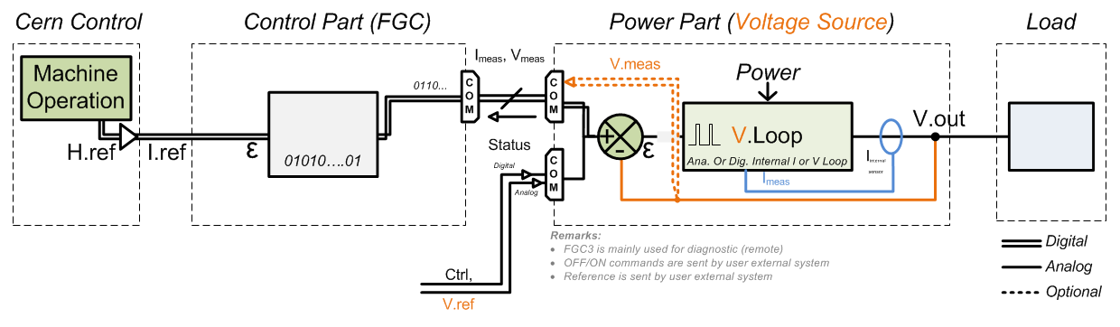
FGC3 is simply used to collect the status, faults of the power converter to help with diagnostic (remote tools).Local RF PLC based system transmit the voltage reference and the ON-OFF commands.
FGC3 Use .vsd
To ensure a high reliability, the converter is based on a N+1 modular structure with a total of three modules rated at 100kW each. It can still work with two modules out of three as the required output power is 200kW. All modules share a common input DC link provided by a three phases diode rectifier coupled with a LC filter. The output of each module is connected to a medium frequency transformer constituted of one primary winding and 24 secondary windings. All the secondary windings (3 x 24) are rectified and connected in series in order to obtain the required output voltage.
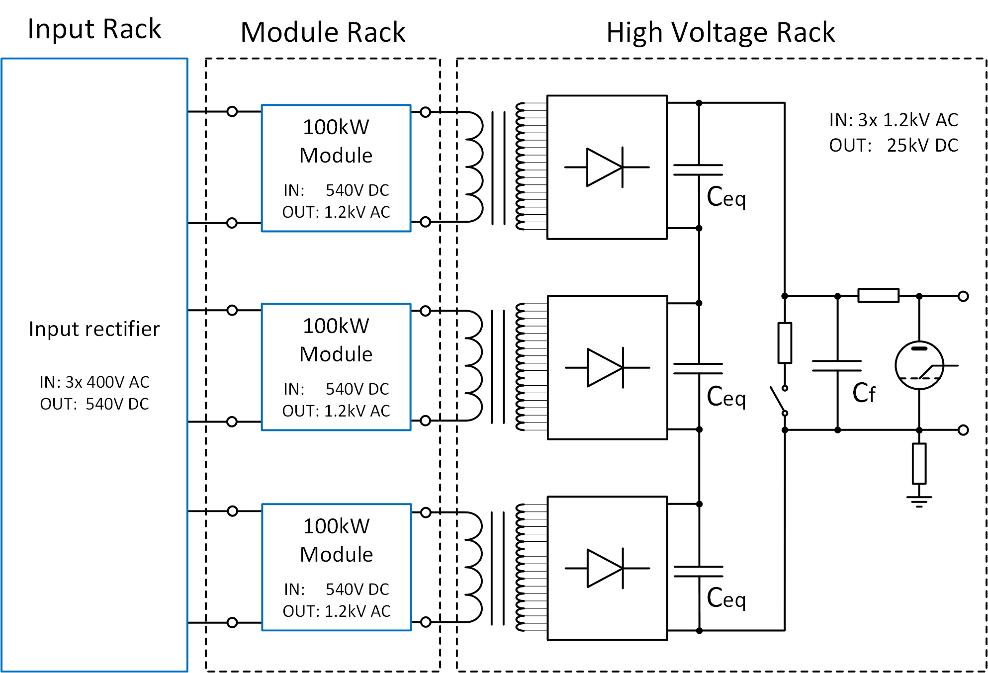
Converter architecture
Power Part
| Power In | 3 ~ 230 V / 450 A.max |
| Power Out | 8 A x 25 kV = 200 kW |
| 50 A.pk for t < 1 ms | |
| Efficiency | 75 %.min |
| Voltage Bandwidth | 100 Hz |
| Insulation Levels | 400 V side: 2.5 kVrms |
| 25 kV side: 40 kVrms | |
| Voltage Output Ripple | [ 20 Hz ; 1 kHz ] → 50 Vrms |
| [ 1 kHz; 130 kHz ] → 5.0 Vrms | |
| [130 kHz; 5 MHz] → 0.5 Vrms | |
| Cooling type | Water Cooling & Forced air ventilation |
| Rack Power Losses | (depending on load operation conditions) |
| Total losses.....30 kW | |
| Water losses....15 kW | |
| Air losses........15 kW | |
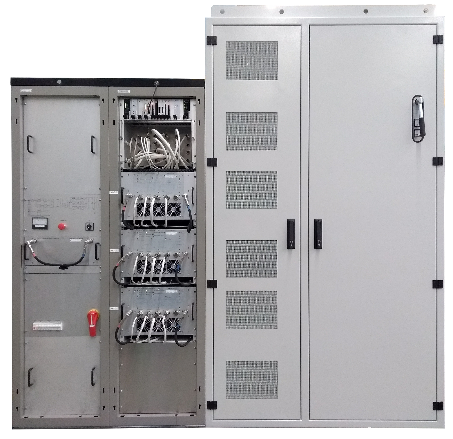
| Converter Weight | Fully equipped converter .................... 2500 kg |
| Converter Size | Whole Converter (3 racks) .................. Width: 2700mm / Depth: 900mm / Height: 2700mm |
Control Part
Control & regulation principles are summarized in a detailled schematics representating only the part involved in the output current regulation scheme.
Load Protection
Power Converter is then expected to:
Power Converter Components .vsd
A power converter is actually a sum of different equipments under several different sections in the SY-EPC group. Proposed solution is based on a Power Rack + Control & Meas Rack; main reason behind this technical choices comes from physical constraints (DCCT Heads location) + fact high precision DCCT electronics are better located in a cool environement (not the case of the power rack, since converters are air cooled).
Magnet Types
| RF | xxxxxx |
Machine Installation
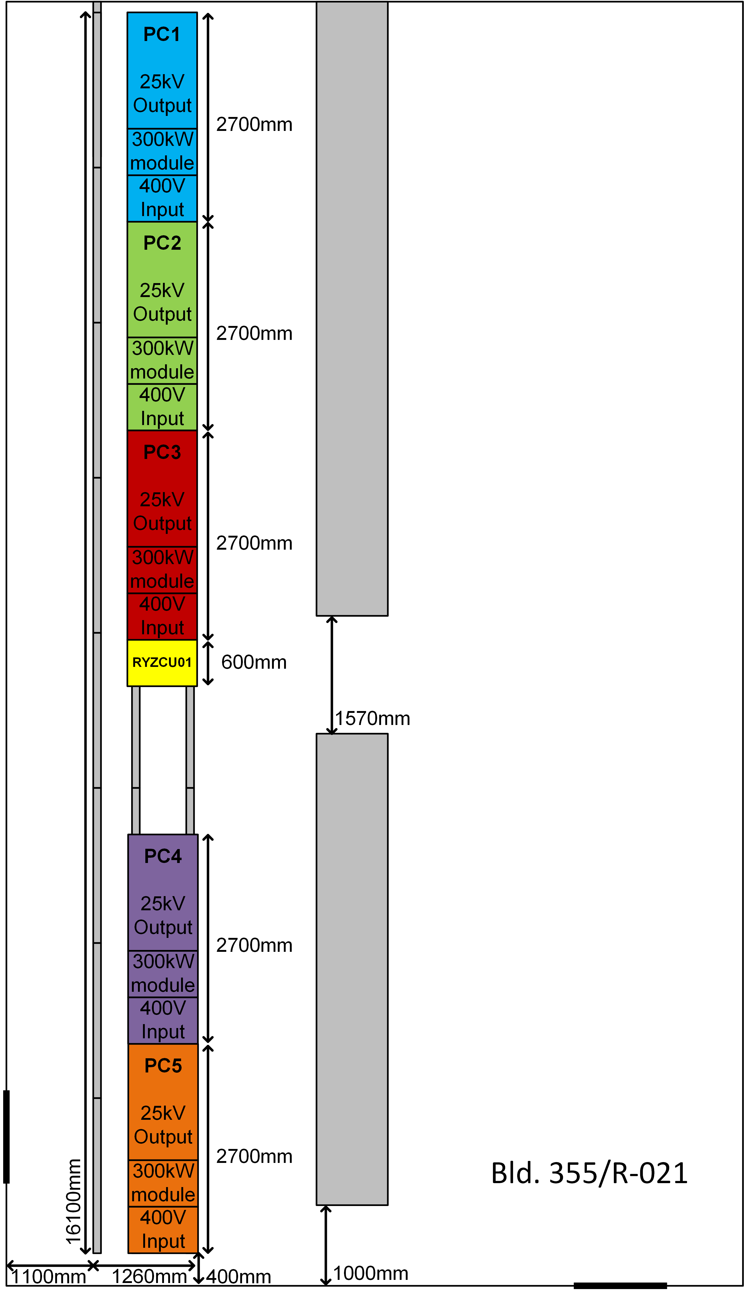
| PS Use | 5 Power Converters (No spare) |
| Location | Bat 355 R-021 |
Production Contract & Contact History
| Developped | Designed & built @ CERN |
| 2013-2016 | |
Converter Circuit Names
| TOP | CHARTE | HTML | CSS | Ver : 13-09-2021 09:30:11 | Webmaster : Michel GEORGES. |