|
HCRAKQS001 / Polarity-Switch A4 |

|
 |
|
 |
|
 |
CERN
|
SY
|
SY-EPC
|
EDMS
|
PROJECTS
|
ODF
/
OOXML
|
|
CERN
|
SY
|
SY-EPC
|
EDMS
|
PROJECTS
|
ODF
/
OOXML
|

|
|
|
||||||||||||||||||||||||||||||||||||||||||||||||||||||||||||||||||||||||||||||||||||
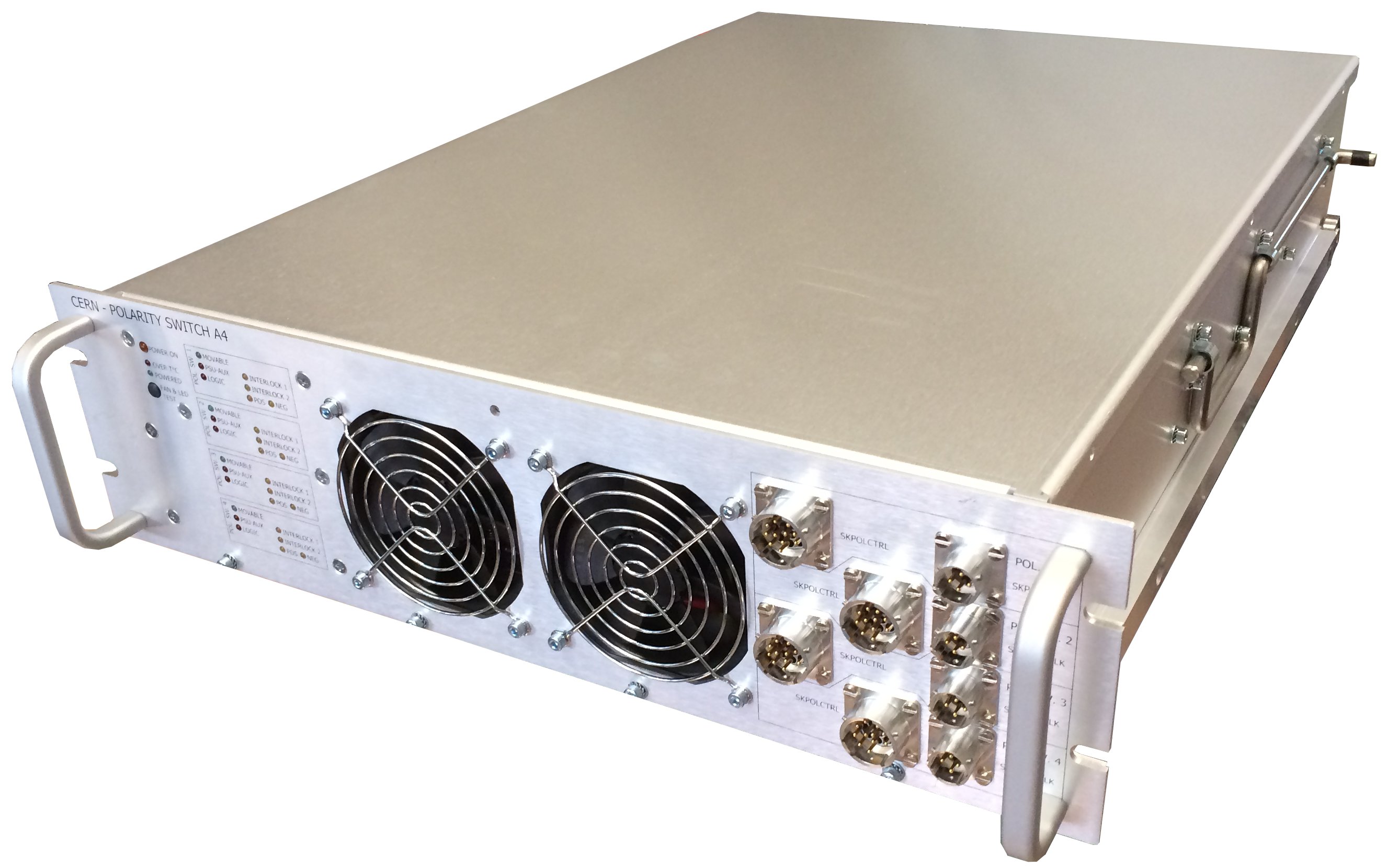
| Polarity‑Switch A4* | Polarity Switch |
| * A4 → 4 circuits managed | |
| Power In | 1 ~ 230 V / 0.5 AMAX |
| Output Rating | PS-A4.4x080: |
| IDC = 80 ADC | |
| V.diode = 300 V (400 V rating) | |
| Control type | Specific Burndy connectors direct signals |
| Optimized for FGC3 / Ethernet And direct control | |
| Single Interlock-type Interface |
 Design & Operation Responsibles
 Benoit FAVRE
|
Responsible-1: Design |
 Yves THUREL
|
Responsible-2 |
| Error processing SSI file |
Integration |
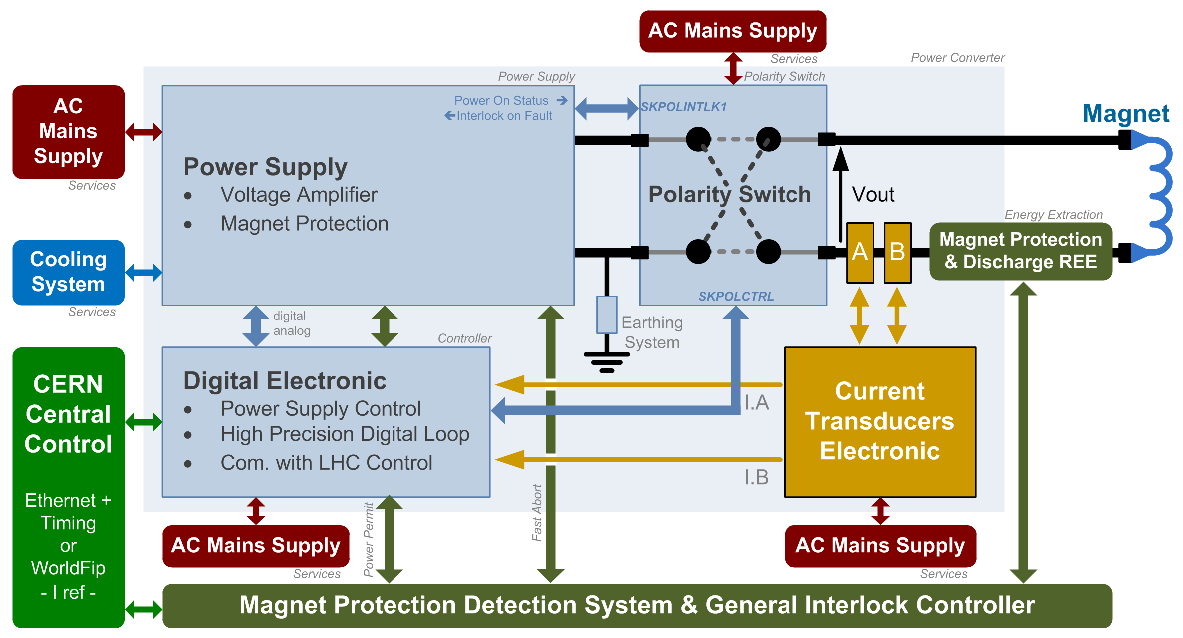
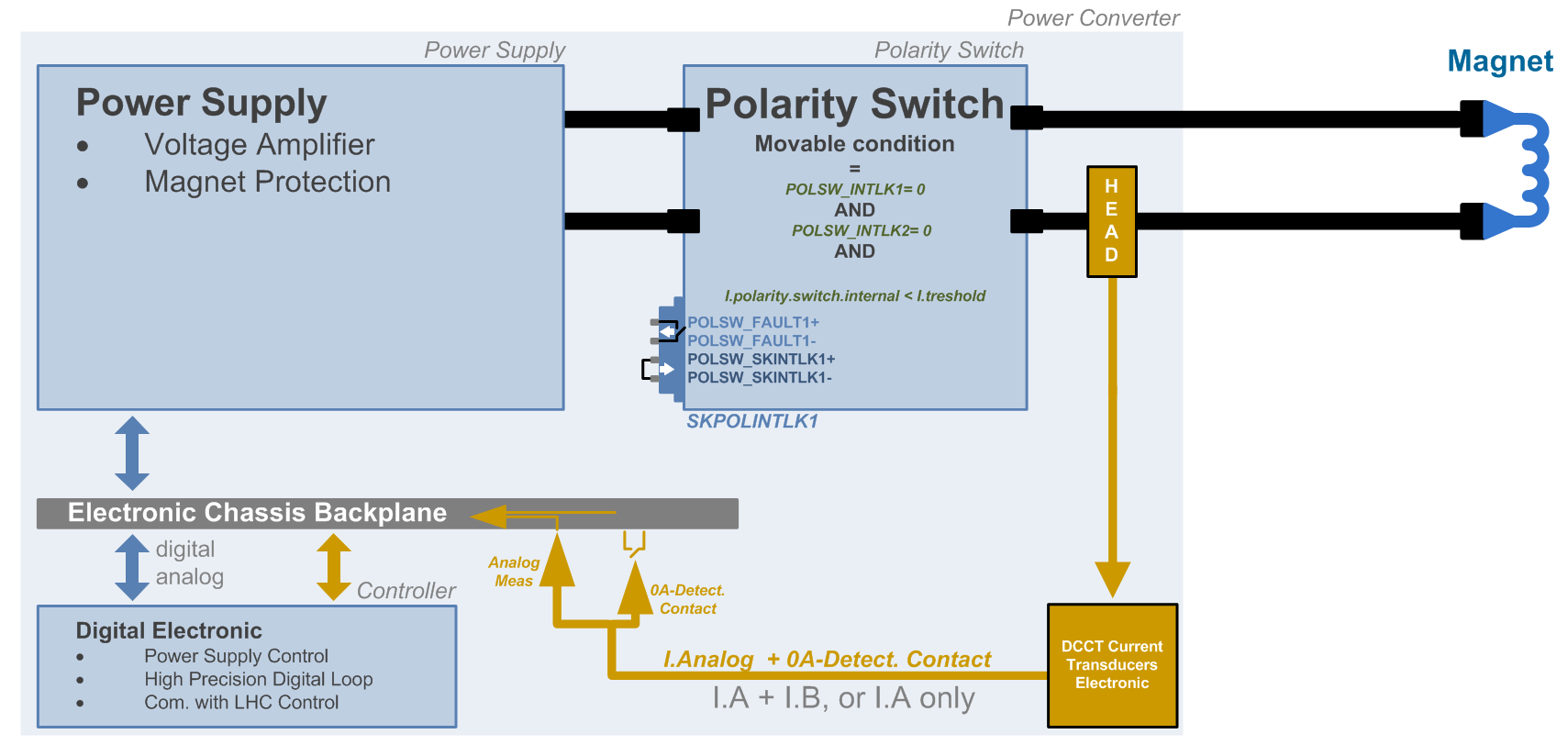
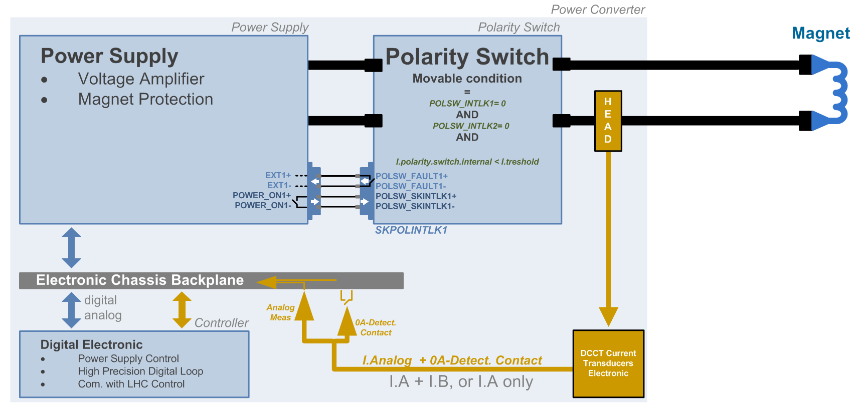
Power Unit Architecture
Polarity Switch is mainly controlled by FGC3, and protects itself against changing state at higher current than 5A.
It can also exchanges signal with Power Module and Discharge system through 2 Interlock Interfaces / connectors.
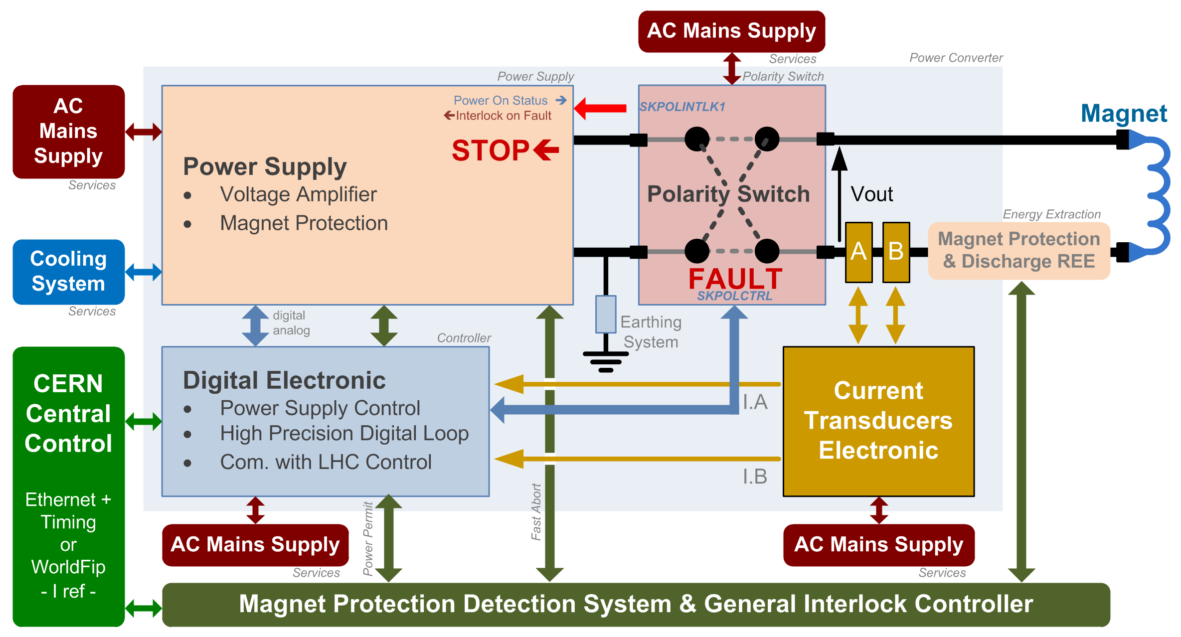
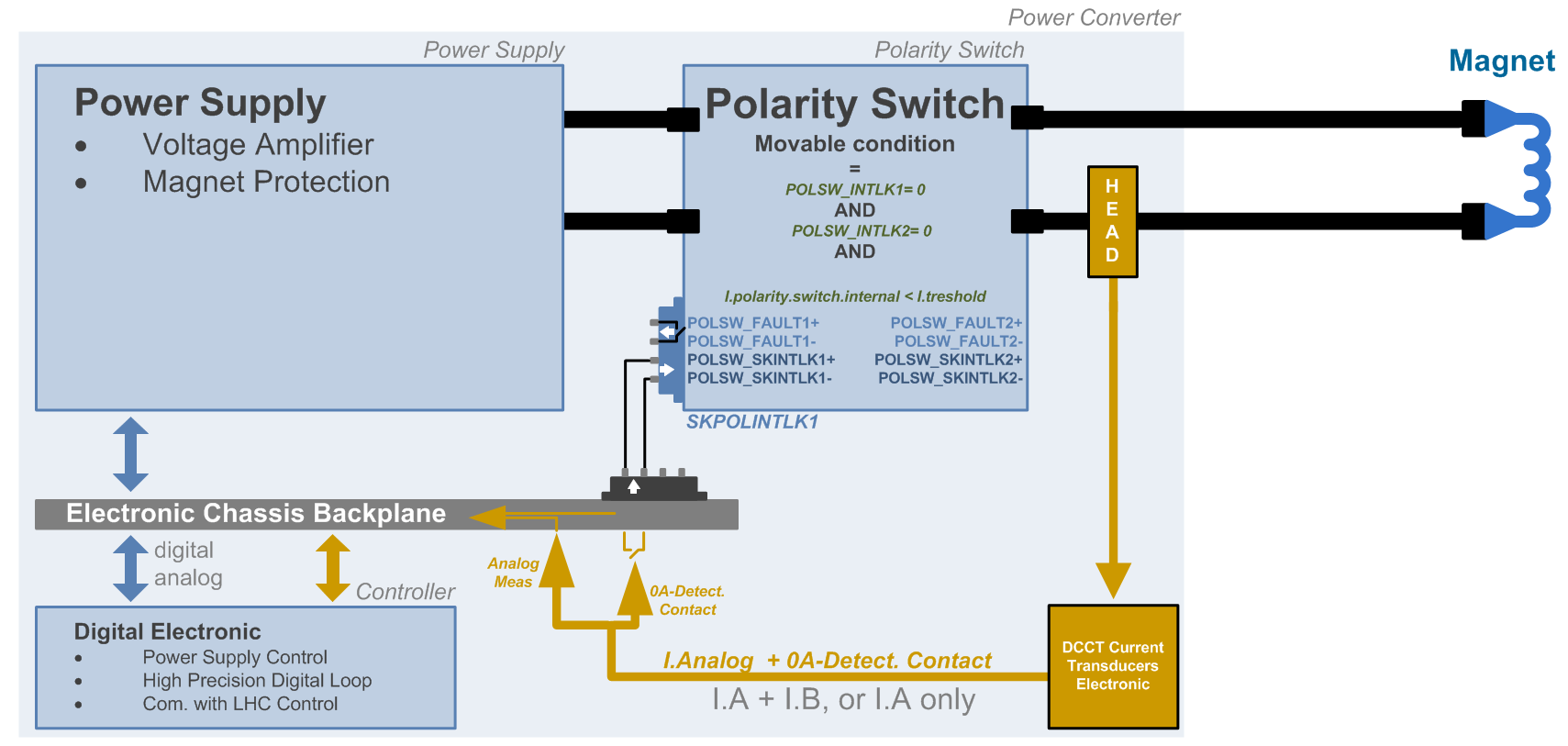
Polarity Switch can send, in case of an internal fault:
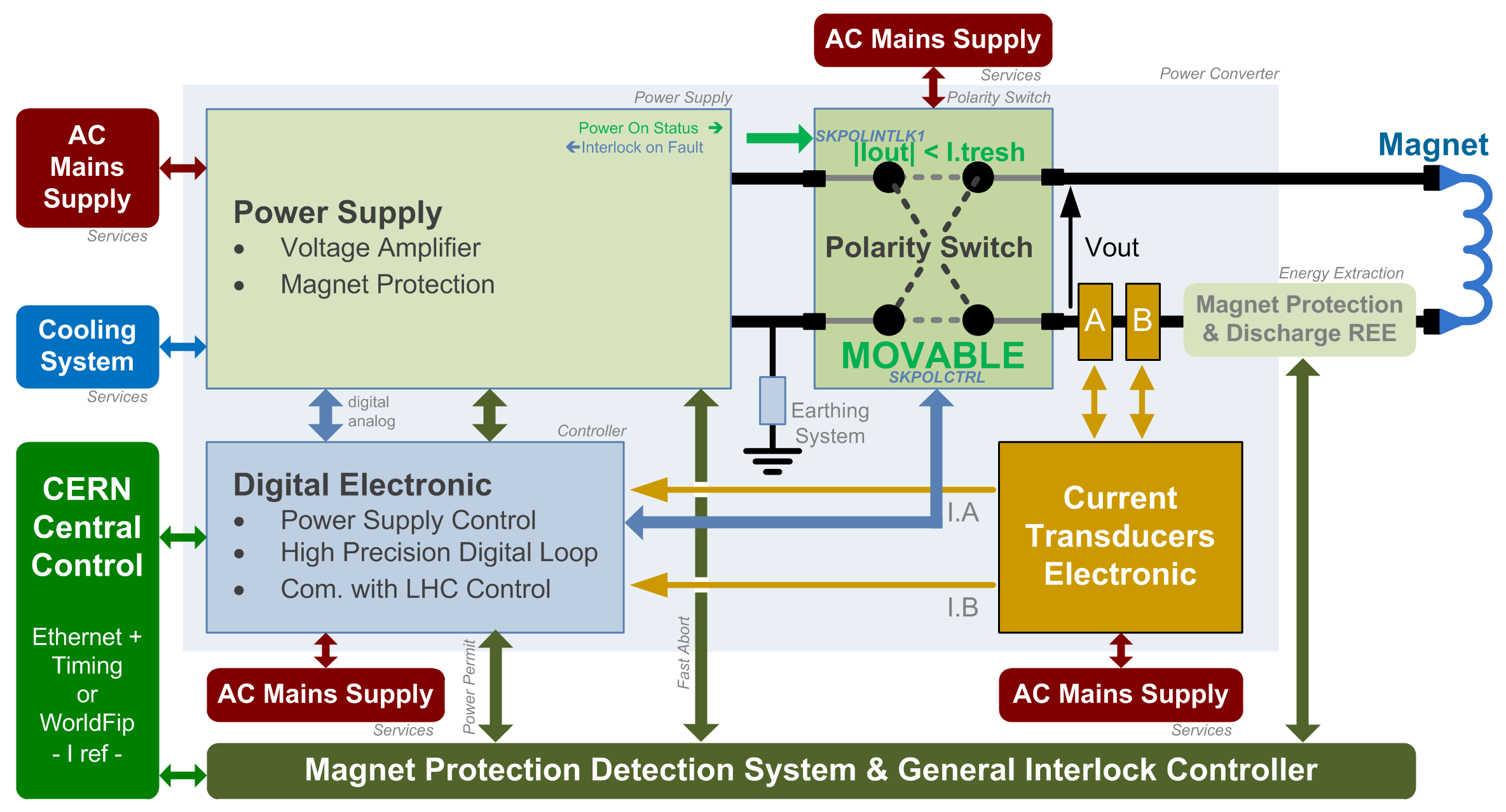
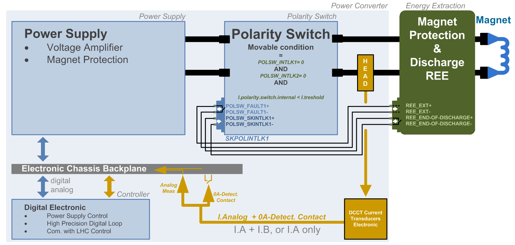
Polarity Switch can receive an interlock freezing its powering status, ignoring any changing state command:
![]() General Schematic
-
General Schematic
-
![]() Polarity Switch In Fault
-
Polarity Switch In Fault
-
![]() Polarity Switch Movable Conditions
Polarity Switch Movable Conditions
Polarity Switch simplified Architecture .vsd
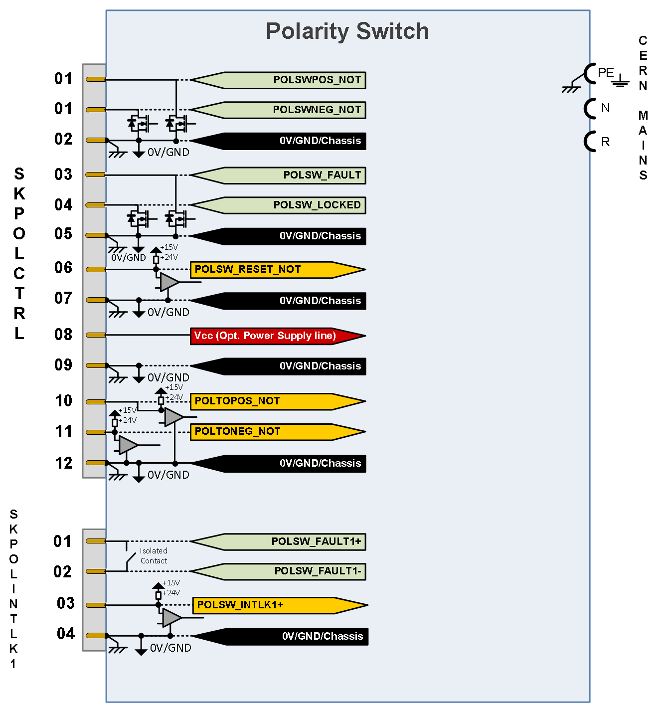
![]() Polarity Switch Connector Pin Assignment
Polarity Switch Connector Pin Assignment
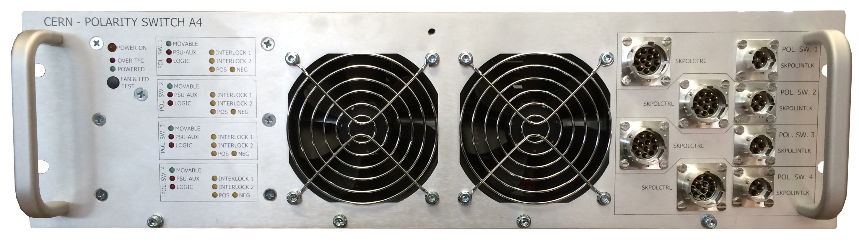
Power Unit
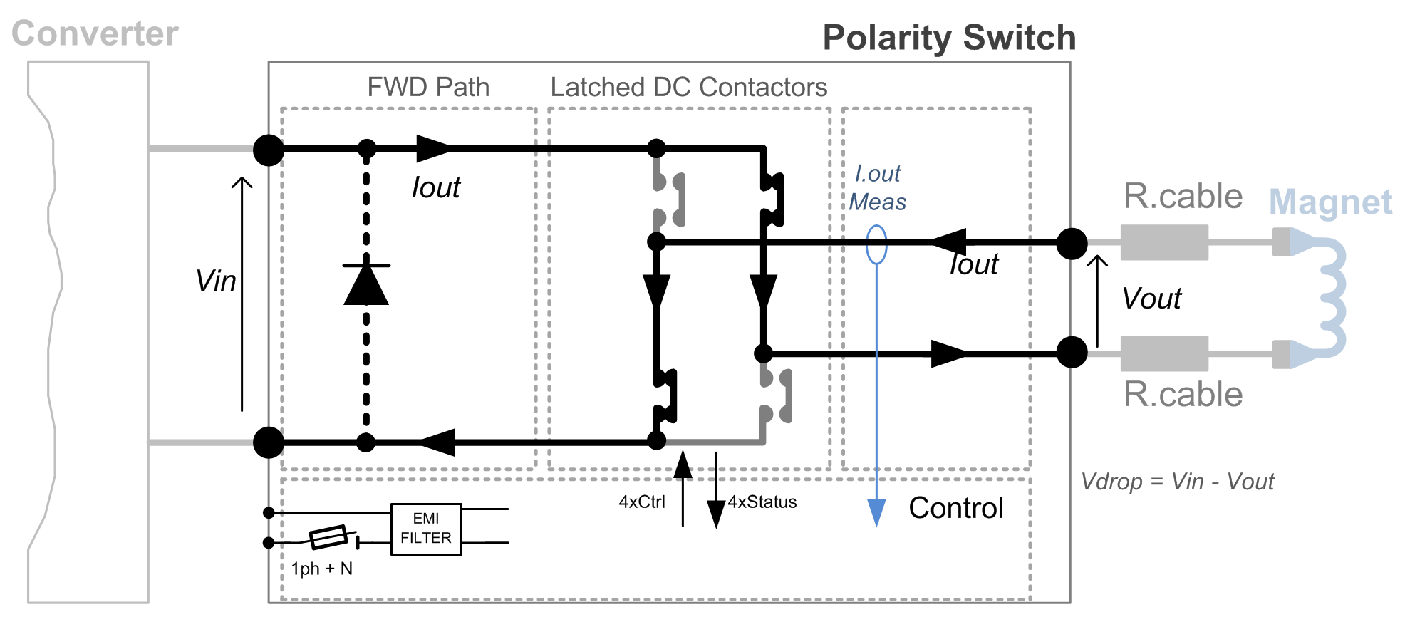
Polarity Switch is based on DC-Contactors (Bi-stable type) providing the capability of inverting the load output polarity.
Power Module is compatible with 19'' standard dimensions.
| Cooling type | Fans |
| Power Module Weight | ≈ 25kg |
See below a quick overview of the schematics.
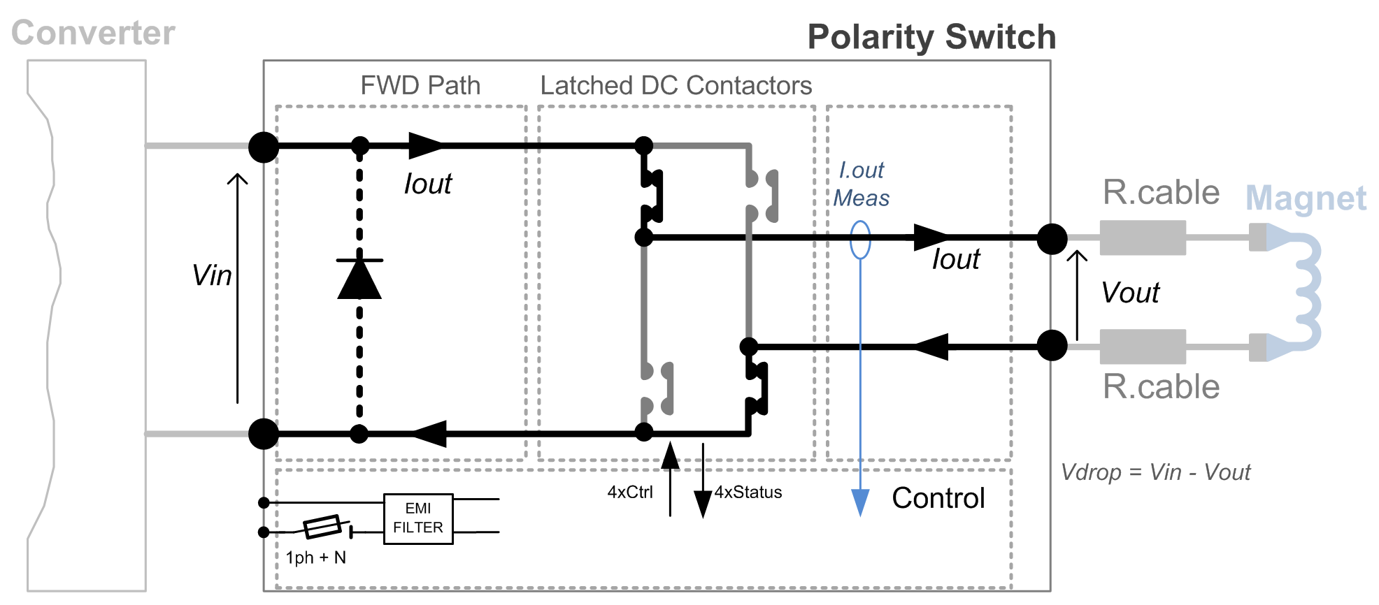
![]() Polarity Switch Pos.
-
Polarity Switch Pos.
-
![]() Polarity Switch Neg
Polarity Switch Neg
Polarity Switch simplified Topology .vsd
Magnet Protection
Polarity Switch is part of magnet protection scheme, even if not directly fully responsible of the monitoring and diagnostic of the superconductive magnet status.
Power Switch is then expected to:
- Not be activated (opening the ouput load current path) while current is not below a treshold limit (sufficiently low not to damage its contact, referring to magnet energy being stored, even at low current)


![]() Case 1
-
Case 1
-
![]() Case 2
-
Case 2
-
![]() Case 3
-
Case 3
-
![]() Case 4
Case 4
Polarity Switch simplified Architecture .vsd
Power Unit Components .vsd
- Power Unit including
- 4x Control Card
- 1x PSU Card
- 1x Front Panel Card
- 16x DC bistable type Contactors
Machine Installation
| Max Air losses | Control Side (incl. fans) | ≈ 70 Watts |
| Conduction Losses (per circuit) | ≈ 40 W = 0.480V * 80 A | |
| Building | Bat xxx |
Production Contract & Contact History
| Production | 2 Pc A4.4x80 |
| 2014 - (BASE - 1 x Unit in operation + 1x unit spare) | http://base.web.cern.ch/|
| Production | 1 Pc A4.4x80 |
| 2014 - Spare internal study |
Converter Circuit Names
| Type | Equipement variations | |||||||
|---|---|---|---|---|---|---|---|---|
| Individual Circuits |
I.nom. per circuit [A] |
Interlock Connectors per circuit |
Internal Power Latched Contactor |
Free Wheel Diode |
Movable Treshold Current [A] |
Rear DC Connection |
Rear AC Connection |
|
| A4.4x080 | 4 | 080 | 1 | GXL14 2-p. Gigavac |
Optional | 1 | CombitacAC+DCDC:100Amax/pin d8 [25; 35] mm² |
|
| A2.2x300 A2.1x300 |
2 1 |
300 | 2 | 2 | ||||
| A1.1x700 | 1 | 700 | MXL14 2-p. Gigavac |
5 | Busbars 40x8mm-M16 |
Burdny 1Ph+N+PE |
||
Overview of the different possible latched contactors studied .xls
| TOP | CHARTE | HTML | CSS | Ver : 18-12-2020 22:21:31 | Webmaster : Michel GEORGES. |