|
RPZEQ, RPAFJ / Mididiscap |

|
 |
|
 |
|
 |
CERN
|
SY
|
SY-EPC
|
EDMS
|
PROJECTS
|
ODF
/
OOXML
|
|
CERN
|
SY
|
SY-EPC
|
EDMS
|
PROJECTS
|
ODF
/
OOXML
|

|
|
|
|||||||||||||||||||||||||||||||||||||||||||||||||||||||||||||||||||||||||||||||||||||
| MIDIDISCAP | Medium size DIScharge CAPacitor converter |
| Power In | 3 ~ 230V/2.75A |
| Power Out | 5ms max (+/- 50A +/-600V) |
| Converter Type | Capacitor Discharge |
| Control type | FGC3 / Ethernet+ |
| Current Accuracy | 200 ppm@ 30 mn |
| 200 ppm@ 24 h | |
| 1000 ppm@ 1 year | |
| (1 ppm=50uA=0.05mA) | |
| Voltage Ripple | 10 mVrms@ f=20Hz-1kHz |
| 60 mVrms@ f=1kHz-130kHz | |
| 7 mVrms@ f=130kHz-5MHz |
 Design & Operation Responsibles
 Serge PITTET
Technical referee, designer
Serge PITTET
Technical referee, designer |
|
 Christophe MACHADO
Responsible 1
Christophe MACHADO
Responsible 1 |
|
 Ludovic CHARNAY
Responsible 2
Ludovic CHARNAY
Responsible 2 |
Power Converter Architecture
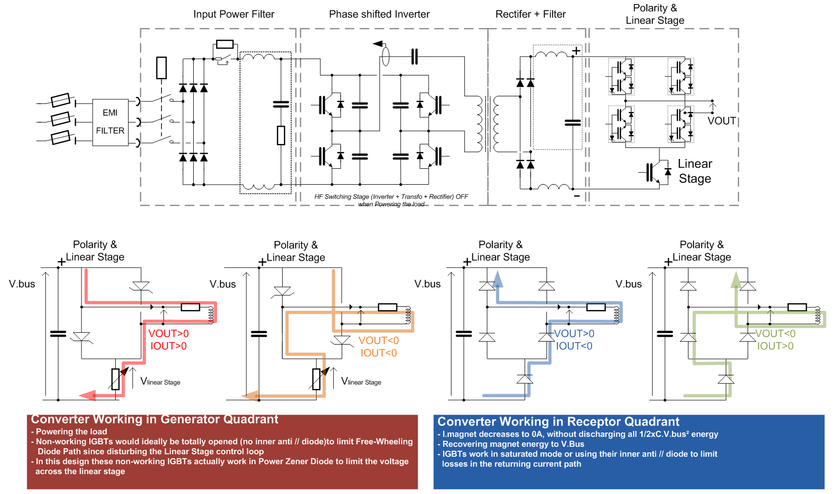
Power Part simplified Architecture / Topology .vsd
Simplified Operation Overview
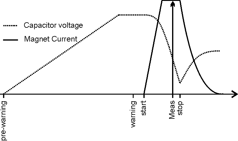
- Simplified Operationnal chronograms
- pre-warning starts charging the capacitor bank.
- warning indicates that the discharge will soon start.
- Start discharging the capacitor bank into the magnet.
- Meas indicates when the current value must be sampled.
- Stop the capacitor discharge. Note that this is a new proposed signal and that it should be optional (the converter will limit the pulse to an internal maximum).
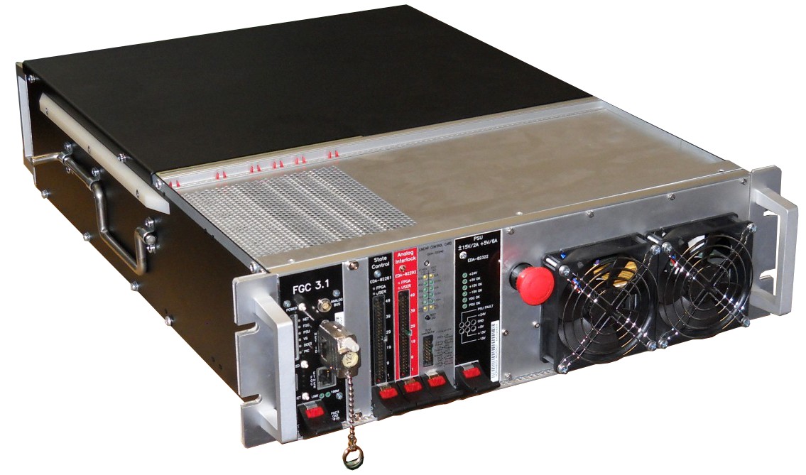
Power Part
Voltage Source is based on a full bridge phase shifted topology followed by a linear stage in series with a fulle bridge to allow the 4 quadrant operation.
One precision resistor is used for the high precision current loop (FGC), and is located directly in the converter.
Converter is compatible with 19'' standard dimensions.
| Power In | 3 ~ 230V/2.75A |
| Power Out | 5ms max (+/- 50A +/-600V) |
| Cooling type | Fans |
| Converter Weight | Power Module ............ 27 kg (FGC Included) |
Power Part simplified Architecture / Topology .vsd
Typical Curves
| Output Voltage Ripple | TBD |
Control Part
Magnet Protection
Power Converter is part of magnet protection scheme, even if not directly fully responsible of the monitoring and diagnostic of the magnet status. WIC (Warm Interlock Controller) can interlock Power Converter if magnet safety requires it.
Power Converter is then expected to:
- Always ensure that external protection system can stop the Power Converter through a safe signal called Fast Abort.
- Stop powering the load in safe way (handling the magnet energy even when stopping, through dedicated system called crowbar). This active system provides a safe resistive discharge path for magnet current (energy).
- Monitor Earth current of the total circuit: converter + load (magnet and its DC cables), and take the right action if threshold reached.
- Earth System
Detection system is an active / passive system, since relying on a converter state-controlled 100mA current source powering a 100Ohms resistor connected between earth and negative polarity of the Power Converter. A common mode voltage is then created, (100mA x 100Ohms = 10V) making possible to detect an earth fault even with converter being OFF (not condamned). Active system is disabled when Power Converter is set STANDBY or ON, with a 10 Ohms resistance series a fuse only being connected between negative polarity and earth.

Earthing System simplified schematic .vsd
Power Converter Components

A power converter is actually a sum of different equipments under several different sections in the SY-EPC group. The modularity is a key factor for easier maintenance with regards to MTTR reduction.
- Power Module
- Digital Controller: FGC3 + FGC3-dongle
- FGC3 Fan unit
Magnet Types
| corrector | TBD |
Machine Installation
| Air losses | Module @ P.nom (incl. FGCs) | 350 Watts |
| Linac 4 Use | 4 Power Converters: DTL | |
| 8 Power Converters: CCDDTL | ||
| 12 Power Converters: PIMS | ||
| 26 Power Converters: TRANSFER Line | ||
| Booster Use | 0 Power Converters | |
| PS Use | 0 Power Converters | |
| AD Use | 0 Power Converters |
Production Contract & Contact History
| Developped |
|
| 2012-2013 | |
|
Serge PITTET
|
|
|
Ludovic CHARNAY
|
|
| Manufactured | Denmark |
| 2012-2013 | |
| CB-svendsen | |
| Production | 60 Pc |
Converter Circuit Names
| TOP | CHARTE | HTML | CSS | Ver : 13-09-2021 09:28:40 | Webmaster : Michel GEORGES. |