|
RPAIC,D,E / MEXICO |

|
 |
|
 |
|
 |
CERN
|
SY
|
SY-EPC
|
EDMS
|
PROJECTS
|
ODF
/
OOXML
|
|
CERN
|
SY
|
SY-EPC
|
EDMS
|
PROJECTS
|
ODF
/
OOXML
|

|
|
|
||||||||||||||||||||||||||||||||||||||||||||||||||||||||||||||||||||||||||||||||||||||||||||||||||||
| MEXICO | MEdium SIze COnverter |
| Power In | 3 x 400V with Neutral / 3A |
| Power Out | 2500 W peak (<100 ms), 1500 W DC |
| RPAIC (MEXICO 12) | ±12.5 A, ±200 V |
| RPAID (MEXICO 25) | ±25 A, ±100 V |
| RPAIE (MEXICO 50) | ±50 A, ±50 V |
| Converter Type | 4 Quadrant |
| Control type | FGC4 / RegFGC / Ethernet+ |
| Series operation | FGC INTER_FGC Properties limited voltage bandwidth (<1 kHz) |
| Parallel operation | Complex, not foreseen (Total current reconstruction, paralleling inner current loops, analogue or digital link between VS_DSPs between VS_DSPs) |
| Output CM voltage | 1200 V isolation, 600 V working |
| Current Accuracy | Class 4 |
| Voltage Ripple | 10 mVrms@ f=20Hz-1kHz |
| 60 mVrms@ f=1kHz-130kHz | |
| 7 mVrms@ f=130kHz-5MHz | |
| Cooling | Air forced |
| Marking | CE |
 Design & Operation Responsibles
| Responsibles: |
 Serge PITTET
|
 Ludovic CHARNAY
|
|
|
|
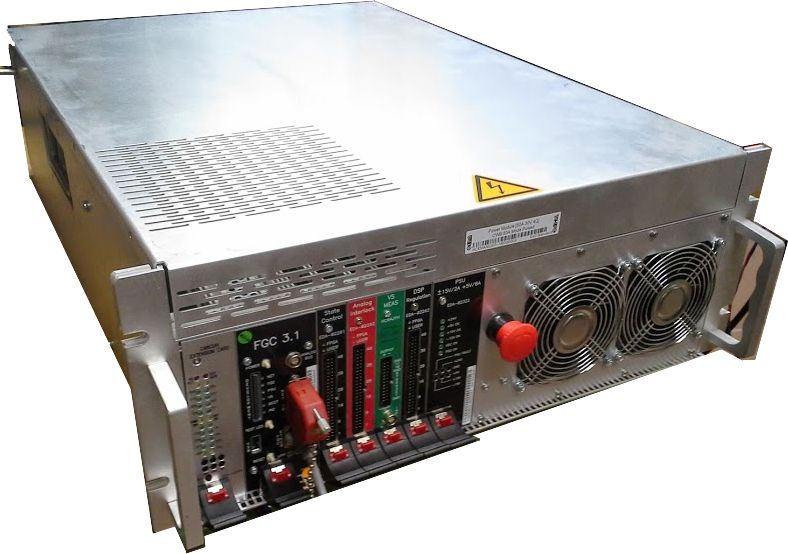
Power Converter Architecture
This Power Converter is used in Injector Machines to power warm magnets, for DC or pulse applications.
Different parts were designed and produced separately, Power Converter being finally integrated in a housing rack, with 3 main parts:
- High Precision Current sensors (DCCTs), able to measure DC or pulse current at the required precision.
- Power Part: Power Rack and its removable Power Module
- A Digital Controller (FGC) using Ethernet bus in charge of:
- The high level control from and to the Cern Control Room
- The high precision digital current loop
- Collecting and reporting all status, faults, and measurements from all the different parts to the remote services, for diagnostic and operation purposes.
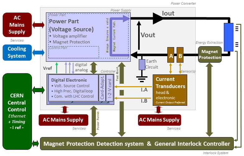
Power Converter simplified Architecture .ppt or .vsdx
Power Part
Voltage Source is based on a full bridge phase shifted topology followed by a 4 quadrant switching stage to allow the 4 quadrant operation.
One DCCT is used for the high precision current loop (FGC), and is located directly in the voltage source, even if not used by it to operate as a pure voltage source.
Converter is compatible with 19'' standard dimensions.
| Power In | 3 x 400V with Neutral / 2.75A |
| Power Out | 2500 W peak, 1500 W DC |
| Cooling type | Fans |
| Converter Weight | Power Module ............ 29 kg (FGC Included) |
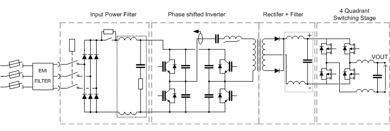
Power Part simplified Architecture / Topology .vsd
Typical Curves
| Output Voltage Ripple | TBD |
Control Part
Control & regulation principles are summarized in a detailled schematics representating only the part involved in the output current regulation scheme. FGC3 control can adapt quite easily with different possible scenarios.


![]() I.Loop, I.sensor = power
-
I.Loop, I.sensor = power
-
![]() I.Loop=fgc, I.sensor=power
-
I.Loop=fgc, I.sensor=power
-
![]() I.Loop=fgc, I.sensor=external
I.Loop=fgc, I.sensor=external
Regulation Control simplified schematic .vsd
High precision current control loop is managed by the digital controller called FGC (Function Generator Controller). This unit includes a high precision Sigma Delta Analog to Digital Converter which digitalize the analog current measurement coming from 1 or 2 Current sensors (DCCTs: DC current Transducer). Precision is then directly relying on sensor precision: current sensors, the ADCs, and the algorithm being used for the regulation loop. Voltage source is then used as a power amplifier, powering the load through a high bandwidth voltage loop.
Magnet Protection
Power Converter is part of magnet protection scheme, even if not directly fully responsible of the monitoring and diagnostic of the magnet status. WIC (Warm Interlock Controller) can interlock Power Converter if magnet safety requires it.
Power Converter is then expected to:
- Always ensure that external protection system can stop the Power Converter through a safe signal called Fast Abort.
- Stop powering the load in safe way (handling the magnet energy even when stopping, through dedicated system called crowbar). This active system provides a safe resistive discharge path for magnet current (energy).
- Monitor Earth current of the total circuit: converter + load (magnet and its DC cables), and take the right action if threshold reached.
- Crowbar
The system is based on a 200 mOhms power resistance connected to two mosfet which are closed when the converter is off or standby.
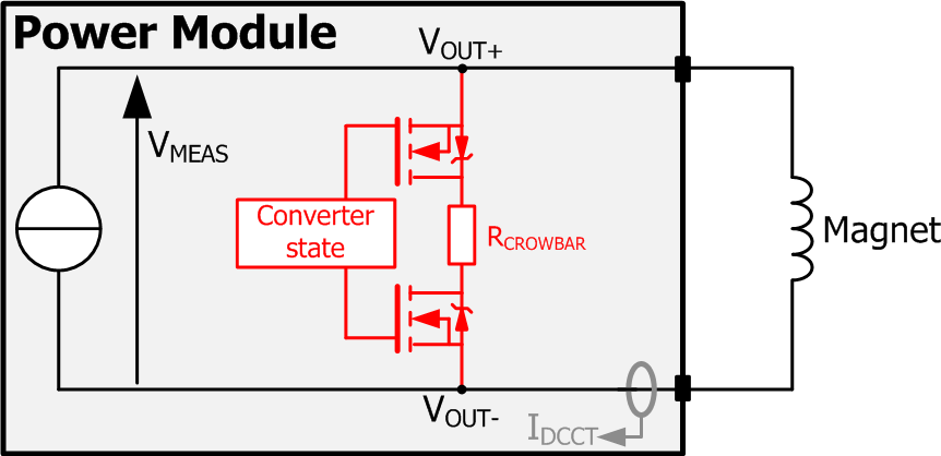
Crowbar System simplified schematic .vsd
- Earth System
This system is based on a two modes detection system: Active (by default) and Passive (configurable). In Active mode, the load is polarized to +10 V versus earth on its output mid-point (common mode). This allows detecting any earthing leakage faulty condition, without the need to energise the circuit for allowing the detection system to operate. A 100 Ohms earthing resistor in series with a 0.1 A fuse connects the mid-point to earth, with this resistance being used as a current sensor (shunt) sensing the circuit earthing leakage current. The system monitors the earthing leakage current to a value of 5 mA maximum allowed. The fuse (0.1 A fast) is provided to limit damage risk on the circuit side in any case and mode (active / passive).
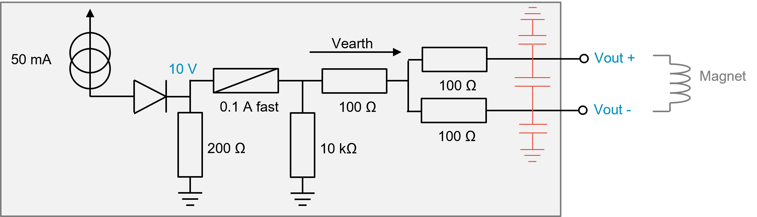
Earthing System simplified schematic .pptx
Power Converter Components
A power converter is actually a sum of different equipments under several different sections in the SY-EPC group. The modularity is a key factor for easier maintenance with regards to MTTR reduction.
- Power Module
- 2x Current sensor: PCB mount DCCT
- Digital Controller: FGC4
Magnet Types
| corrector | TBD |
Machine Installation
| Air losses | Module @ P.nom (incl. FGCs) | 350 Watts |
| Water losses | Module @ P.nom (incl. FGCs) | none |
| AD Use | xx+x MEXICO Power Converters | |
| Spares A7 |
x MEXICO Power Converters x MEXICO Power Converters |
Production Contract & Contact History
| Developped |
|
|
| 2021 | ||
|
Serge PITTET
|
||
|
Ludovic CHARNAY
|
||
| Production | - |
xx MEXICO Power Converters xx MEXICO Power Converters |
| Current requests | MEXICO12 Power Converters |
003+1 for AD consolidation |
| MEXICO25 Power Converters |
007+2 for AD consolidation |
|
| Pending requests | MEXICO12 Power Converters |
008+2 for LEIR consolidation |
| MEXICO25 Power Converters |
012+2 for AD trims consolidation 040+8 for LEIR consolidation 008+2 for LINAC4 consolidation 004+2 for LINAC4 source test stand |
|
| MEXICO50 Power Converters |
040+6 for AWAKE 2 Electron Line 017+3 for AWAKE 2 Helicon Plasma Source 016+4 for LEIR consolidation |
Converter Circuit Names
| TOP | CHARTE | HTML | CSS | Ver : 13-01-2023 17:39:37 | Webmaster : Michel GEORGES. |