|
RPHE / LHC13kA-18V |

|
 |
|
 |
|
 |
CERN
|
SY
|
SY-EPC
|
EDMS
|
PROJECTS
|
ODF
/
OOXML
|
|
CERN
|
SY
|
SY-EPC
|
EDMS
|
PROJECTS
|
ODF
/
OOXML
|

|
|
|
||||||||||||||||||||||||||||||||||||||||||||||||||||||||||||||||||||||
| Power In | 3 ~ 230V/420A |
| Power Out | 13kA 18V |
| Converter Type | 1 Quadrant |
| Control type | FGC2 / WorldFip |
| Current Accuracy | 03 ppm@ 30 mn |
| 05 ppm@ 24 h | |
| 50 (20 with calibration) ppm@ 1 year | |
| (1 ppm=13mA) |
 Design & Operation Responsibles
| 1st Intervention |
 Piquet SY-EPC LHC
|
| Responsibles: |
 Vincent BARBET
|
 Ludovic CHARNAY
|
|
 Valérie MONTABONNET
|
|
|
|
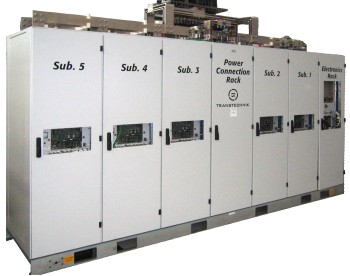
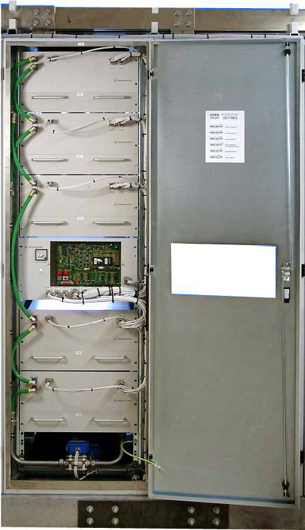
Power Converter Architecture
This Power Converter is used in LHC Machine to power superconductive magnets. It is located in the LHC underground installation, close to the loads to limit cable losses in the underground installation.
Different parts were designed and produced separately, Power Converter being finally integrated in a housing rack, with 3 main parts:
- High Precision Current sensors: DCCTs, able to measure DC current at the required precision.
- Power Part: Power Rack and its removable Power Module
- A Digital Controller (FGC) using WorldFip bus in charge of:
- The high level control from and to the Cern Control Room
- The high precision digital current loop
- Collecting and reporting all status, faults, and measurements from all the different parts to the remote services, for diagnostic and operation purposes.
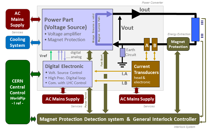
Power Converter simplified Architecture .ppt
Power Part
A high current switch mode power converter, designed for powering of superconducting loads requiring only positive current and positive voltage control (1 quadrant). The converter is constructed from a modular architecture composed of 3.25kA power modules. The converter is water cooled, and is thus ideally suited to situations where air losses must be carefully managed. Designed for underground operation, extensive remote diagnostics have been foreseen to allow efficient monitoring and fault diagnostics without requiring being present locally.
| Power In | 3 ~ 230V/420A |
| Power Out | 13kA 18V |
| Cooling type | Water Cooling + forced air ventilation on output modules* |
| Nominal Water Condition → 45 l/min @ 3.0 bars of Differential Pressure Drop. * | |
| In/Out rack connection: DN32. | |
| * added by CERN to increase their lifetime (LEM + diodes). | |
| Total Converter Weight | 2600kg (without any module) |
| 3800kg (with all modules) | |
Find below the detail of weight and dimensions of all the converter power modules ...
Power Converter is normally assembled using a n+1 Power Bricks [+3.25kA +18V] to provide active redundancy in case of one subconverter is lost. For example, a [+13kA +18V] is composed of 5x [+3.25kA +18V] Power Brick, working as current source being controlled by a Voltage Source main control.
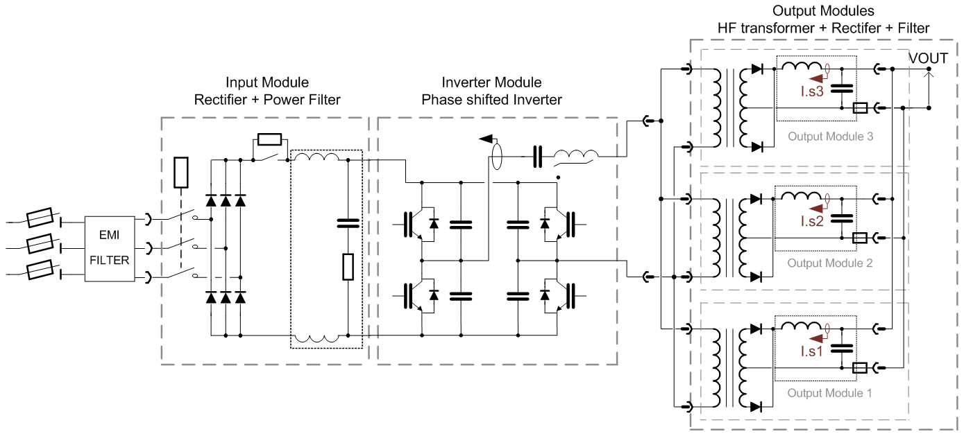
[3.25kA 18V] Sub-Converter simplified Architecture / Topology .vsd
Power Brick is actually a high frequency current source (7-8kHz) controlled by a 1kHz bandwidth voltage loop. One can notice that Power Brick is actually a current cource in its structure, even if voltage source capacitors are located in this block for mechanical reasons. Representation below gives a symbolic structure of the power converter, clarifying the cascade loops.
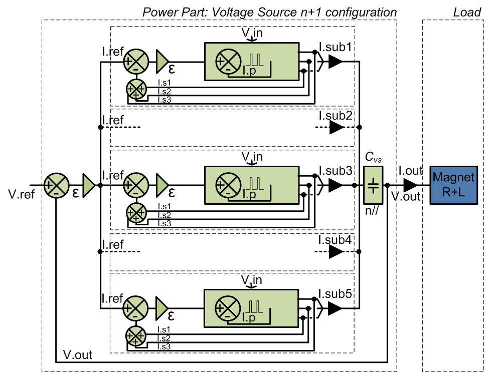
[13kA 18V] Voltage Source simplified Architecture / Topology .vsd
Typical Curves
| Sub-Converter Output Module Curves | |
| Output Power Rectifier Voltage V0x | [200A 1.05V] V01, V2 , [400A 2.1V] V01, V2 , [1kA 5.3V] V01, V2 |
Control Part
Control & regulation principles are summarized in a detailled schematics representating only the part involved in the output current regulation scheme.
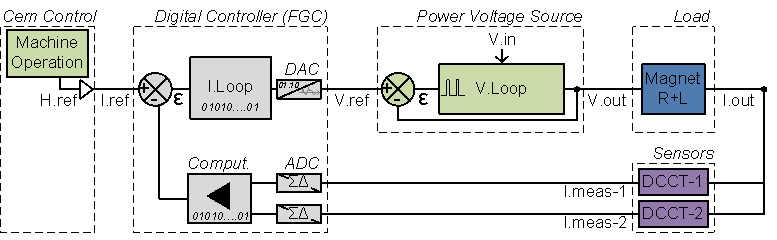
Regulation Control simplified schematic .vsd
High precision current control loop is managed by the digital controller called FGC (Function Generator Controller). This unit includes a high precision Sigma Delta Analog to Digital Converter which digitalize the analog current measurement coming from 2 DCCTs (DC current Transducer). Precision is then directly relying on sensor precision: DCCT, the ADCs, and the algorithm being used for the regulation loop. Voltage source is then used as a power amplifier, powering the load through a high bandwidth voltage loop (>500Hz).
Magnet Protection
Power Converter is part of magnet protection scheme, even if not directly fully responsible of the monitoring and diagnostic of the superconductive magnet status. Dedicated systems QPS (Quench Protection System) + PIC (Power Interlock Controller) can interlock Power Converter if magnet safety requires it.
Power Converter is then expected to:
- Always ensure that external protection system can stop the Power Converter through a safe signal called Fast Abort. This redundant signal uses 2 paths to interlock and stop the converter and its redundancy is checked each time it acts.
- Stop powering the load in safe way (handling the magnet energy even when stopping, through free-wheeling diode path).
- Monitor Earth current of the total circuit: converter + load (magnet and its DC cables), and take the right action if threshold reached.
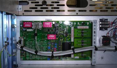
- Free Wheeling Diode Safe Paths
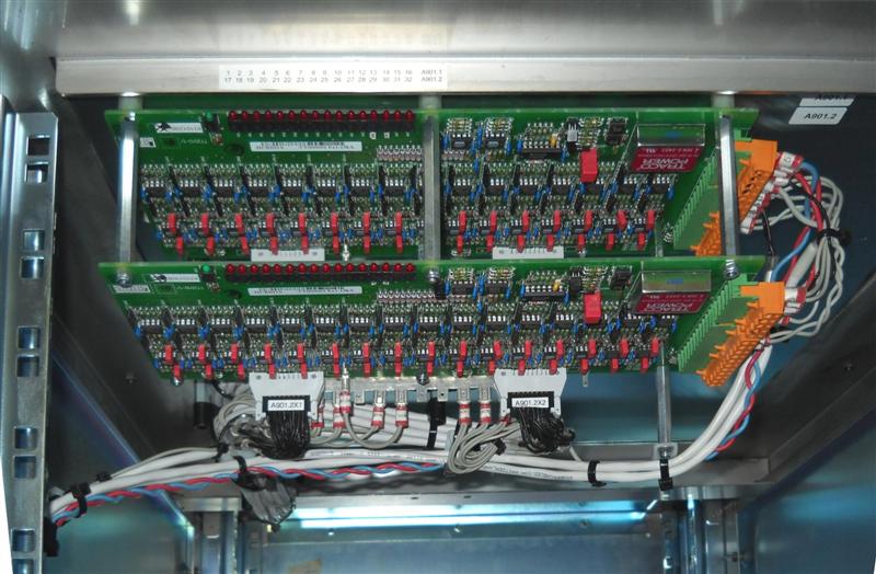
Each free wheel diode module is electronically monitored for open-circuit and short-circuit by a Free Wheeling Diode Monitoring Card.The monitoring principle is as follows:
- The current inside each diode module is measured through a FWD monitoring card using voltage taps over each diode modules connection cable (which works as a shunt): maximum 16 channels per FWD monitoring card.
- The average value of the diode module currents of a same FWD monitoring card is calculated.
- Each individual diode module current is compared to the average. If the difference exceeds a preset threshold, then the corresponding diode is considered faulty and signalled by a red Led on the FWD monitoring card. A global FWD fault alarm is also generated by the card.
- When several FWD monitoring cards are used, the global alarm of each FWD monitoring card is connected in a daisy chain generating one FWD fault at the level of the Common Control Electronics for remote diagnostic.
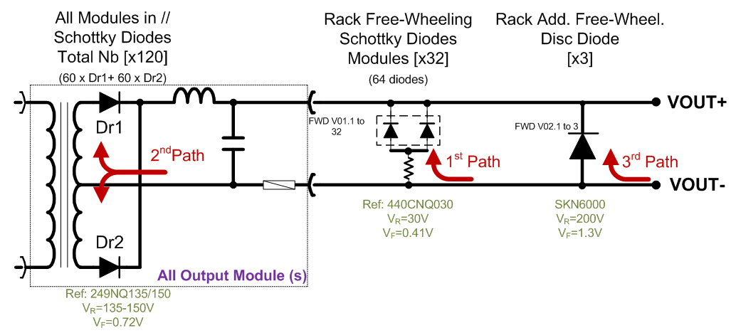
FWD simplified schematic .vsd
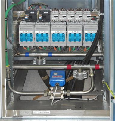
- Earth System
The circuit injects a 100 mA DC current on a grounded resistive branch, resulting in a common mode voltage at the output circuit easing the earthing fault detection. Output circuit Common mode voltage is, without any earth fault, around 10V (=100 mA x 100 Ohms), and is not relying on load operation, making possible to detect an earth fault even with converter being OFF. (OFF, not condamned).
If an earth fault occurs on the output circuit, a faulty current will be deviated from the initial path back to earth by using the shunt 10 Ohms resistor path (monitored for detecting this fault).
Overcurrent protection is achieved through a 1A-100V fast fuse in series in the path provided for the earthing fault current.
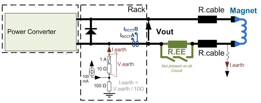
Earthing System simplified schematic .vsd
Power Converter Components .vsd
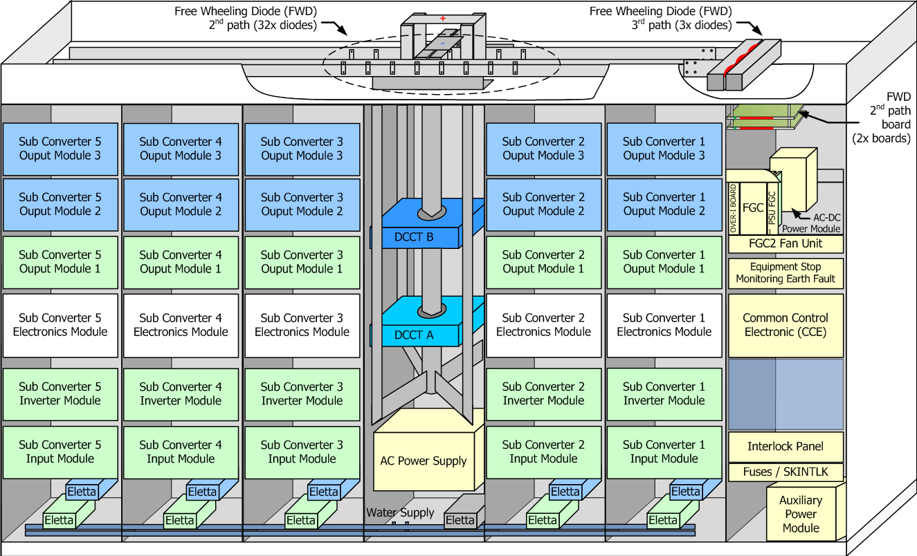
A power converter is actually a sum of different equipments under several different sections in the SY-EPC group. The modularity is a key factor for easier maintenance with regards to LHC tunnel access conditions.
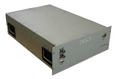
- Power Converter Rack
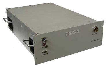
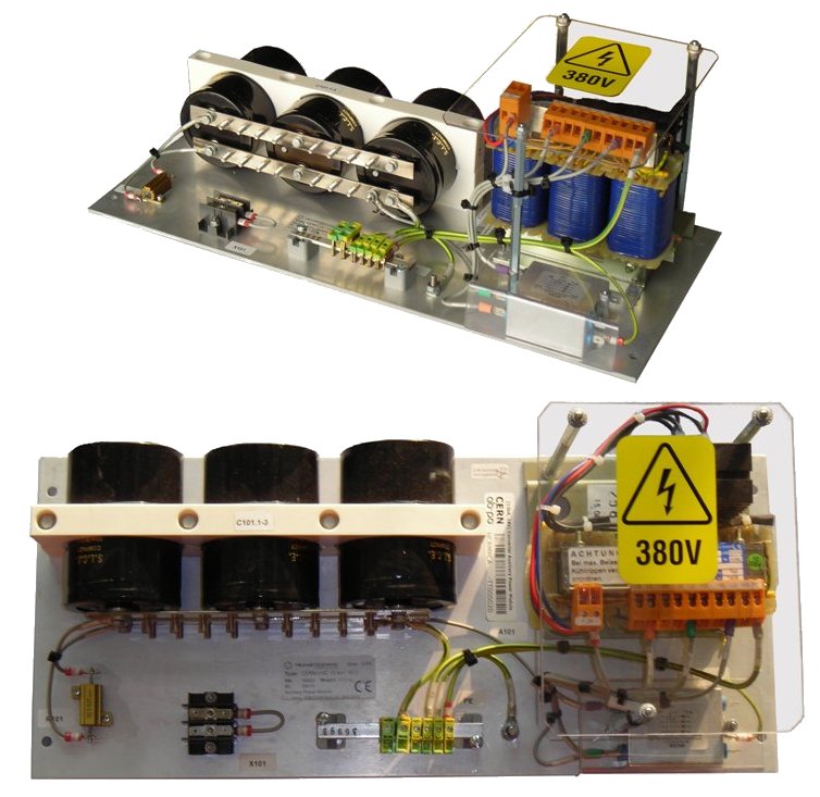
- Voltage Source Unit
- FGC2 Fan tray unit
- 2x Current sensors: DCCTs Heads
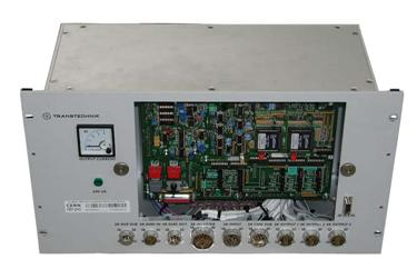
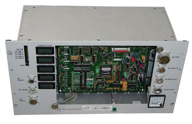
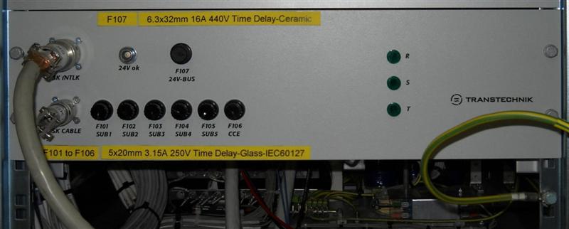
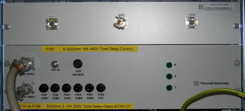
- Electronic Chassis (Ref: HCRFEFA - Type 5) .edms
- Digital Controller: FGC2
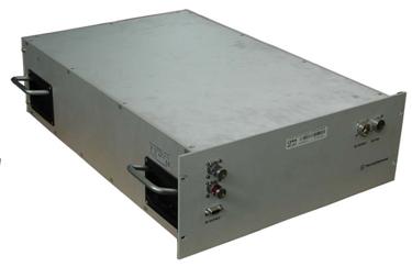
- AC/DC Power Module
- PSU FGC Tri-volt
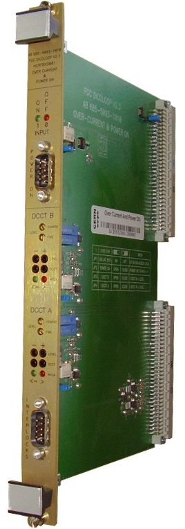
- Over Current Protection Card (Over-I)
- Calibration Rack
- 2x Current sensors: DCCTs Electronics
- Sigma Delta 22 bits ADC
Magnet Types
| Main Quadrupole (Focusing and Defocusing) | RQF, RQD |
Machine Installation
| LHC Use | 16 Power Converters |
| Radiation Safe Locations (272) | UA23 (2), UA27 (2), UA43 (2), UA47 (2),
UA63 (2), UA67 (2), UA83 (2), UA87 (2) |
Production Contract & Contact History
| Developped | Transtechnik |
| 2001-2003 | |
| Manufactured | HOLZKIRCHEN and BUECHLBERG , GERMANY |
| Transtechnik | |
| Contract Reference | F521 |
| Production | 16+2 Pc |
| CERN Contact |
Valérie MONTABONNET
|
|
Ludovic CHARNAY
|
Converter Circuit Names
| TOP | CHARTE | HTML | CSS | Ver : 04-09-2023 17:22:34 | Webmaster : Michel GEORGES. |