|
RPAFM Cute |

|
 |
|
 |
|
 |
CERN
|
SY
|
SY-EPC
|
EDMS
|
PROJECTS
|
ODF
/
OOXML
|
|
CERN
|
SY
|
SY-EPC
|
EDMS
|
PROJECTS
|
ODF
/
OOXML
|

|
|
|
||||||||||||||||||||||||||||||||||||||||||||||||||||

| Cute | Converter Usually Tiny Enough |
| Power In | 3 ~ 230V/0.5A[0.4..1A] |
| Power Out | [±12.5 A; ±15 V] |
| Converter Type | 4 Quadrant |
| Control type | FGC3 / Ethernet+ |
| Current Accuracy | 100 ppm@ 30 mn |
| 200 ppm@ 24 h | |
| 1000 ppm@ 1 year | |
| (1 ppm=12 uA=0.012 mA) | |
| Voltage Ripple | 2.0 mVrms@ f=10Hz-50Hz |
| ≤8.0 mVrms@ f=50Hz-150kHz | |
| ≤2.0 mVrms@ f=130kHz-5MHz |
 Design & Operation Responsibles
 Yves THUREL
|
|
 Edwin ROHRICH
|
|
 Nicolas Kuczerowski [2019-2023] Nicolas Kuczerowski [2019-2023] |
Power Converter Architecture
This Power Converter is used in Experiences, Injector Machines to power warm magnets or even Superconductive Magnet, for DC or pulse applications.
Different parts were designed and produced separately, with the option of a Power Converter being finally integrated in a housing rack, with 3 main parts:
- Power Part:
- Power Rack (AC & DC distribution, interconnections)
- Ideally Removable Power Module when suitable
- CERN Digital Controller (FGC3):
- The high level control from and to the Cern Control Room (using Ethernet+ bus)
- The high precision digital current loop (when a voltage source is controlled)
- Collecting and reporting all status, faults, and measurements from all the different parts to the remote services, for diagnostic and operation purposes.
- High Precision Current sensor(s) (DCCTs)
- Measuring DC or pulse current at the required precision.
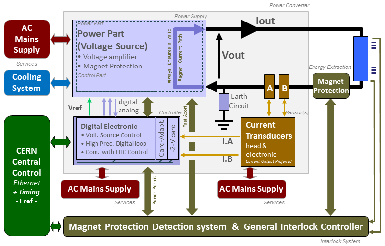
Power Converter simplified Architecture .ppt or .vsdx
Power Source
Voltage Source Power Module is based on an economic solution involving commercial off the shelves AC-DC power units, followed by a full bridge 4-quadrant stage, and a brake shopper to absorb energy from the load if required.
Two DCCTs can be used for the Power Converter precision current loop, and are located in a dedicated board for an easy maintenance.
Converter can be powered with a standard AC-3Ph Burndy connected cable, and its form factor is compatible with an installation of 3 Power Module (including the FGC3 Controller) per row in a 19'' width rack. Since the converter is 4 U height, up to xx power converter can be installed in a single 2 meter high 19'' rack.
| Power In | 3 ~ 230V/0A[..] |
| Power Out | [±12.5 A; ±15 V] |
| Cooling type | Fans |
| Converter Weight | Power Module ............ [5; 7] kg |

Power Part simplified Architecture / Topology .vsd


S1 = ON & S4 = ON. Energy is delivered to the load from input source, and to L1 & L2.


Chronogram [t0x t1] [t1 t2] [t2 t3] [t3 t4] [t4 t5] [t5 t6] [t6 t7] [t7 t8] [t8 tx]
Powering simplified schematic .vsd
Controller
Control & regulation principles are summarized in a detailled schematics representating only the part involved in the output current regulation scheme. FGC3 control can adapt quite easily with different possible scenarios.


![]() I.Loop, I.sensor = power
-
I.Loop, I.sensor = power
-
![]() I.Loop=fgc, I.sensor=power
-
I.Loop=fgc, I.sensor=power
-
![]() I.Loop=fgc, I.sensor=external
I.Loop=fgc, I.sensor=external
Regulation Control simplified schematic .vsd
High precision current control loop is managed by the digital controller called FGC (Function Generator Controller). This unit includes a high precision Sigma Delta Analog to Digital Converter which digitalize the analog current measurement coming from 1 or 2 Current sensors (DCCTs: DC current Transducer). Precision is then directly relying on sensor precision: current sensors, the ADCs, and the algorithm being used for the regulation loop. Voltage source is then used as a power amplifier, powering the load through a high bandwidth voltage loop.
Magnet Protection
Power Converter is part of magnet protection scheme, even if not directly fully responsible of the monitoring and diagnostic of the superconductive magnet status. Dedicated systems QPS (Quench Protection System) + PIC/WIC (Power/Warm Interlock Controller) can interlock Power Converter if magnet safety requires it.
Power Converter is then expected to:
- Always ensure that external protection system can stop the Power Converter through a safe signal called Fast Abort. This redundant signal uses 2 paths to interlock and stop the converter and its redundancy is checked each time it acts. It directly acts on AC Contactor bobbin, ensuring its opening as required.
- Stop powering the load in safe way (handling the magnet energy even when stopping, through dedicated system called Free Wheeling Diode Safe Paths). This passive system based on different paths using several free-wheeling diodes in the rack provide a safe discharge path for magnet current (energy).
- Monitor Earth current of the total circuit: converter + load (magnet and its DC cables), and take the right action if threshold reached.
- Earth System
Detection system is an active system, since relying on a 100 mA current source powering a 100 Ohms resistor connected between earth and negative polarity of the Power Converter. A common mode voltage is then created, (100 mA x 100 Ohms) making possible to detect an earth fault even with converter being OFF. (OFF, not condamned).

Earthing System
 Connected
-
Not Connected
Connected
-
Not Connected
Earthing System simplified schematic .vsd

Power Converter Components .vsd

A power converter is actually a sum of different equipments under several different sections in the SY-EPC group. The modularity is a key factor for easier maintenance with regards to MTTR reduction.
Power Converter Rack can accept up to 24x Power Converters, or up to 21x Power Converters, with FGC3 switch and pulse injector control items, limiting FGCEther cabling to the rack environment. (Cost reduction, and easier maintenance).
- Power Converter 42U Rack including:
- RMAAN Power Module, including each:
- Digital Controller: FGC3 + FGC3-dongle (1x FGC3 / Power Converter)
- Card VS PSU (1x PSU for 2 FGC3) HCRFAAB EDA-02322
- Card VS I.MEAS (including two DCCTs, with their burden and scaling electronics)
- A Rack AC Distribution Top Panel providing:
- AC fuses (3Ph+N fuseholder) for 6x Power Sources
- AC fuses (1Ph+N)/24V.dc for Rack fans (including main contactor for Eq. Stop functionality).
- A Rack Config Panel providing:
- A central Power Rack Equipment Stop Button (stopping full rack).
- A Rack Bottom Panel including:
- AC Rack Main connexion from CERN service
- RMAAN Power Module, including each:
Magnet Types
Machine Installation
| Air losses | 1x Full Rack @ P.nom (incl. 24x (Power Converters) | 2500 Watts |
| ELENA Use | 30 Power Converters | |
| Building | Bat 193 |
Production Contract & Contact History
| Power Modules & Racks Design & Production | CERN [60; 100] Pc |
Converter Circuit Names
| TOP | CHARTE | HTML | CSS | Ver : 23-12-2023 15:50:49 | Webmaster : Michel GEORGES. |