|
RPADC Compass |

|
 |
|
 |
|
 |
CERN
|
SY
|
SY-EPC
|
EDMS
|
PROJECTS
|
ODF
/
OOXML
|
|
CERN
|
SY
|
SY-EPC
|
EDMS
|
PROJECTS
|
ODF
/
OOXML
|

|
|
| ||||||||||||||||||||||||||||||||||||||||||||||||||||||||||||||||||||||||||||||||||||||||||||||||||||||||||||||||||||||||||||||||||||||||||||||||||||||||||||||||||||
| COMBO | COMmercial Based cOnverter |
| Converters | |

 Common Power Converters Characteristics
| Power In | 3 ~ 230 V / 32 A |
| Converter Type | 1 Quadrant + *Pol. Switch |
| Control type | FGC3 / FGCEther |
| Current Accuracy | 10 ppm@ 30 mn |
| 20 ppm@ 8 h | |
| 50 ppm@ 24 h | |
| 500 ppm@ 1 year | |
| (1 ppm=0.8mA) |
Dipole Power Converter Characteristics
| Machine Name | RPADC.EHN2.RDIP.COMPASS |
| FGCEther Address 1 | |
| Power Out | +700 A, +14 V * |
| -700 A, -14 V * | |
| (700 A limited by polarity switch) |
Solenoid Power Converter Characteristics
| Machine Name | RPADC.EHN2.RSOL.COMPASS |
| FGCEther Address 2 | |
| Power Out | +700 A, +14 V * |
| -700 A, -14 V * | |
| (700 A limited by polarity switch) |
Design & Operation Responsibles
 Yves THUREL
|
Interface EPC <=> Compass |
 Benoit FAVRE
|
Rack + Polarity Switch, Integration, Commissioning, Operation |
 Edwin ROHRICH
|
COMBO-Technical manager |
 Nicolas KUCZEROWSKI
|
COMBO-Expert designer |
Power Converter Architecture
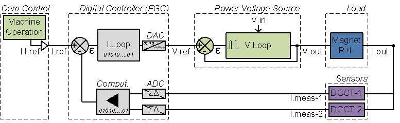
Control & regulation principles are summarized in a detailled schematics representating only the part involved in the output current regulation scheme. FGC3 control can adapt quite easily with different possible scenarios.


![]() I.Loop, I.sensor = power
-
I.Loop, I.sensor = power
-
![]() I.Loop=fgc, I.sensor=power
-
I.Loop=fgc, I.sensor=power
-
![]() I.Loop=fgc, I.sensor=external
I.Loop=fgc, I.sensor=external
Regulation Control simplified schematic .vsd
High precision current control loop is managed by the digital controller called FGC (Function Generator Controller). This unit includes a high precision Sigma Delta Analog to Digital Converter which digitalize the analog current measurement coming from 1 or 2 Current sensors (DCCTs: DC current Transducer). Precision is then directly relying on sensor precision: current sensors, the ADCs, and the algorithm being used for the regulation loop. Voltage source is then used as a power amplifier, powering the load through a high bandwidth voltage loop.
![]() Converter SKINTLK Connector Pin Assignment
Converter SKINTLK Connector Pin Assignment


Power Part
The system proposed is capable to handle a resetable fault, or also AC mains cut for several seconds, not loosing too much current in the magnet (then saving time for de-ramping + ramping again). The capability of restarting with the converter while the load is in free-whell mode has to be proved to ensure scenario is valid, and magnet protection scheme is adequate. REE system can be launched in case of a Quench requiring energy discharge, or in case Power Converter is definitively dead and to save time. A safety crowbar is placed between the polarity switch and the load, to prevent any severe crash in case of a DC Contactor malfunction.
| Power In | 3 ~ 230 V / 32 A.max @ 2 x 14 V x 700 A |
| Power Out | 2x (+700 A +14 V) = 19 600 Watts |
| Cooling type | Forced air ventilation |
| Rack Power Losses | [200; 2000] Watts (depending on load operation conditions) |
| Converter Weight | Bare Rack ........................... TBD kg (Power Modules and full equipped electronic chassis excluded) |
| Delta Power Module ........... 27 kg | |
| Polarity Switch A1.700 ....... 25 kg | |
| Electronic Chassis .... xx kg (FG3 Chassis + 2x FGC3s + 2x PSUs + 2 V2V DCCT Cards) |
Solenoid


Normal Operation
![]() Ramping Up or DC
|
Ramping Up or DC
|
![]() Ramping Down
Ramping Down
Fault Cases
![]() Fast Discharge
|
Fast Discharge
|
![]() very long discharge
very long discharge
Powering System simplified schematic .vsd & .xls
(Ramping Down sequence detailed proposal .pdf)
Dipole


Normal Operation
![]() Ramping Up or DC
|
Ramping Up or DC
|
![]() Ramping Down
Ramping Down
Fault Cases
![]() Fast Discharge
Fast Discharge
Powering System simplified schematic .vsd & .xls
Typical Curves / Measurements
| Output Voltage Ripple .txt | [ 5A 50mV ] V 150MHz: 10us / 1ms - 30MHz: 2ms - I [9; 150] kHz / [150 kHz; 30 MHz] |
| [ 700A 3.6V ] V 150MHz: 10us / 1ms - 30MHz: 2ms - I IAB: std, FFT | |
| Output Currrent Ripple .txt | [ 700A 3.6V ] I Spy: Ripple / FFT |
| Output Currrent Tracking .txt | 600A → 700A, di/dt = 5A/s I Spy: End of ramp |
| EMC: AC Conducted Noise .txt | 2x (700 A; 4 V) [9; 150] kHz / [150 kHz; 30 MHz] |
| EMC: AC Burst Effect on I.out .txt | 2x (700 A; 4 V) [0,1,2,4] kV applied on AC 3Ph-Side (.xls) |
| Earth to DC Neg Pol. FFT .txt | 5ADC Floating , 700ADC Floating |
| Voltage source bandwidth Vout/Vref | Voltage Bandwidth |
| Voltage Source Efficiency vs Output Power | Efficiency Graph, (.xls) |
Control Part
Control & regulation principles are summarized in a detailled schematics representating only the part involved in the output current regulation scheme.
Control & regulation principles are summarized in a detailled schematics representating only the part involved in the output current regulation scheme.
Regulation Control simplified schematic .vsd
High precision current control loop is managed by the digital controller called FGC (Function Generator Controller). This unit includes a high precision Sigma Delta Analog to Digital Converter which digitalize the analog current measurement coming from 2 DCCTs (DC current Transducer). Precision is then directly relying on sensor precision: DCCT, the ADCs, and the algorithm being used for the regulation loop. Voltage source is then used as a power amplifier, powering the load through a high bandwidth voltage loop (>500Hz).
Magnet Protection
Power Converter is part of magnet protection scheme, even if not directly fully responsible of the monitoring and diagnostic of the superconductive magnet status. Dedicated systems QPS (Quench Protection System) + PIC (Power Interlock Controller) can interlock Power Converter if magnet safety requires it.
Power Converter is then expected to:
- Always ensure that external protection system can stop the Power Converter through a safe signal called Fast Abort. This redundant signal uses 2 paths to interlock and stop the converter and its redundancy is checked each time it acts. It directly acts on AC Contactor bobbin, ensuring their opening as required.
- Always ensure a safe path exists, on the power converter side, even if experience ensure this at the level of the magnet side. It is important to notice that Free Wheeling Diode provided in the Polarity Switch cannot handle the complete and very long discharge of the superconductive magnets.
Earthing Circuit
Earth Detection system is managed by experience. DC Output Lines are delivered being floating.
Power Converter Fault Events
Power magnet protection strategy shall not lead to Power Converter failure. Principal risk can be to over-stress the free-wheeling diode of the Polarity Switch, in case the converter is stopped without fault, while at maximum current. The Energy Extraction System using both POWERING FAILURE (SKINTLK) and POLSW_FAULT1 or POLSW_FAULT2 (SKPOLINTLK1/2) shall prevent dramatic consequences by protecting the power converter. Other powering units faulty standard cases are covered in the table below.
| Case | Load Operation | |||||||
|---|---|---|---|---|---|---|---|---|
| State | Powering Failure | State | Fault | CP(1&2) | CL | CR | ||
| Normal Operation | Safe | 0 | Safe | 0 | Closed | Opened | Closed | Powered |
| Fault on Power Units | Fault | 1 | Safe | 0 | Opened | Closed | Closed | Very Long Discharge. It is possible that Power Units failed on AC Phase loss, and experience can recover them without discharging the magnet. Load is disconnected from the powering system. |
| Fault on Pol. Switch | Safe | 1 | Fault | 1 | Opened | Closed / Opened | Opened | Fast Discharge. A polarity switch fault can be internal free wheeling diodes being close to being destroyed, requiring an immediate disconnection from the load current. Since a polarity switch is a main event, and has to be analyzed, magnet is completly discharged with a Fast Discharge. |
Interfaces between Power Converter and Energy Extraction System in case of Power Units or Polary Switch Faults
Power Converter Components .vsd
A power converter is actually a sum of different equipments under several different sections in the SY-EPC group. Proposed solution is based on a Power Rack + Control & Meas Rack; main reason behind this technical choices comes from physical constraints (DCCT Heads location) + fact high precision DCCT electronics are better located in a cool environement (not the case of the power rack, since converters are air cooled).
- EPC Power Rack of 2 power converters including
 Front View
|
Rear View
Front View
|
Rear View

- 1x Rack 45U
- Datasheet Rack Atos Evolution Series .pdf
- 4x Delta-Electronika Power Module 15V 400A
- 2x Polarity Switches A1.700
- 1x Power Converter = 1x Polarity Switch
- 1x Rack AC distribution Front Panel providing:
- 1x AC Breaker per Power Converter (2x in total)
- 1x AC Breaker for Global Rack electronic crate.
- 1x Rack A.U.E. (UPS Stop) Panel providing:
- A push button to stop the UPS powered system with the capability
to also cut the Power AC departure (contactor at AC Dist. level)
- A push button to stop the UPS powered system with the capability
- 1x Rack DC Grounding System (rear view) providing:
- A way to easily ground DC Connexion to earth in a safe way.
- 1x Rack Config Front Panel providing:
- A central Power Rack Equipment Stop Button
- Individual earthing system configuration for up to 4x Power Converters.
- 1x Controller / Electronic Chassis (Type x) including cards:
- 2x Digital Controllers FGC3 + FGC3-dongle (1x FGC3 / Power Converter)
- 2x VS V2V (1x V2V for 2x DCCTs) HCRAKAB EDA-02710
- 1x VS PSU (1x PSU for 2 FGC3) HCRFAAB EDA-02322
- 1x COMBO Config Panel (Type 2cvs2&2):
- 1x Dual Earthing Detection System:
- 2x detection system in 1 2U-unit provided by experience.
- A Rack Bottom Panel including:
- Interlock System Connections to be reviewed.
- 1x Rack 45U

- EPC Measurement Rack including
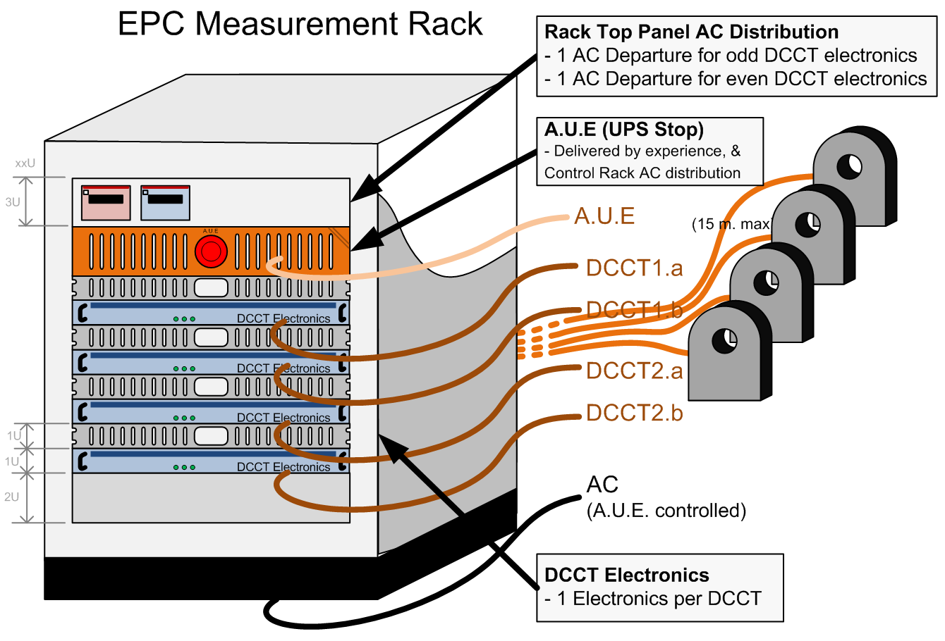
- 1x Rack 18..22U
- Datasheet Rack Atos Evolution Series .pdf
- 1x Rack AC distribution Front Panel providing:
- 1x AC Breaker per Odd DCCT of each Converter
- 1x AC Breaker per even DCCT of each Converter
- 1x Rack A.U.E. (UPS Stop) Panel providing:
- A push button to stop the UPS powered system with the capability
to also cut the Power AC departure (contactor at AC Dist. level)
- A push button to stop the UPS powered system with the capability
- 4x DCCT Electronics
- 2 DCCTs per Power Converter
- 1x Rack 18..22U

- EPC Control Units to be integrated in experience IT-rack

- 1x Gateway
- 1x FGC3 Switch
- 1x FGC3 Pulse Injector
Magnet Types
| Compass Experience | xxxxxx |
Machine Installation
| Compass Use | 1 Complete Rack including 2 Power Converters (solenoid + dipole) |
Production Contract & Contact History
| Developped | Designed & built @ CERN |
| 2013 | |
| Upgraded | Modified to fit with COMBO parts |
| 2017 | |
Old Design Compass Typical Curves / Measurements
| Output Voltage Ripple .txt | [ 5A 50mV ] V 150MHz: 10us / 1ms - 30MHz: 2ms - I [9; 150] kHz / [150 kHz; 30 MHz] |
| [ 700A 3.6V ] V 150MHz: 10us / 1ms - 30MHz: 2ms - I IAB: std, FFT | |
| Output Currrent Ripple .txt | [ 700A 3.6V ] I Spy: Ripple / FFT |
| Output Currrent Tracking .txt | 600A → 700A, di/dt = 5A/s I Spy: End of ramp |
| EMC: AC Conducted Noise .txt | 2x (700 A; 4 V) [9; 150] kHz / [150 kHz; 30 MHz] |
| EMC: AC Burst Effect on I.out .txt | 2x (700 A; 4 V) [0,1,2,4] kV applied on AC 3Ph-Side (.xls) |
| Earth to DC Neg Pol. FFT .txt | 5ADC Floating , 700ADC Floating |
| Voltage source bandwidth Vout/Vref | Voltage Bandwidth |
| Voltage Source Efficiency vs Output Power | Efficiency Graph, (.xls) |
_thermal-map.png)
_thermal-map.png)
_thermal-map.png)
_thermal-map.png)
_thermal-map.png)
Converter Circuit Names
| TOP | CHARTE | HTML | CSS | Ver : 03-05-2022 09:55:42 | Webmaster : Michel GEORGES. |